114 XFC G4 2103335 Rev AB
6.7.1 Step by Step Instructions
In the following procedure, the common name for a component or its jumper number if available (abbreviated J) or part is
followed by a number in parentheses. This refers to the call out item number referenced on each drawing.
To replace the flow computer battery pack:
Connect the PC running PCCU32 to the flow computer with either an MMI cable (RS-232), a USB cable or an
Ethernet cable.
Open PCCU.
Collect the data from the unit as described in section 6.2.1, Data collection (page 108).
Back up configuration files as described in section 6.2.2, Back up configuration files (save) in page 108.6.2.2
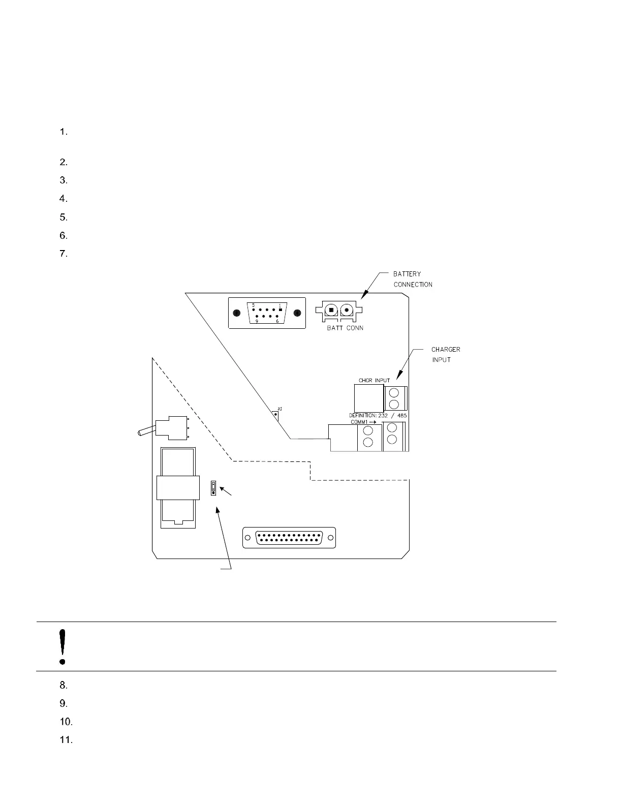
Ensure the J13 memory backup jumper covers the top two pins (Figure 86). This enables the memory backup.
Verify “LL” battery alarm is not being displayed on the LCD
Measure the lithium battery with a Multi Meter ensuring it is > 3.0V.
Figure 86: XFC
G4
Electronic Board Maintenance Connections
NOTICE – Loss of data. When removing the battery, do not remove, or disable the lithium battery from the
board. This will prevent any historical data from being lost.
Disconnect the battery charger from the XFC
G4
panel terminals EXT CHGR +/- J5.
Disconnect the Battery Cable from the XFC
G4
panel connector J1, before removing the battery pack.
Loosen the three mounting screws. Note: It is not necessary to completely remove the screws.
Remove the battery compartment cover (Figure 87: item 18).
J1
J15 I/O EXP
J5
J4
XIMV INTERFACE
(-)
(+)
BT1
1
J13
3
Jumpering across pins 1 & 2 of J1 enables
lithium backup of RAM memory. If lithium
backup is disabled, powering the unit
down will cause a Cold Boot.
1
13
14
25
J9
Lithium Battery Enable
OFF
ON
S1
 Loading...


