70 XFC G4 2103335 Rev AB
IMPORTANT NOTE: Leaks in the tubing or connections will introduce errors when calibrating transducers.
Mount the flow computer to the direct mount manifold using the instructions in section 4.5, Direct Mount Installation for
Gas Orifice.
Leak check all tubing connections before calibrating.
The static pressure input lines are installed.
IMPORTANT NOTE: Leaks in the static pressure connections and tubing will introduce errors in transducer
readings.
4.9 Battery Pack Installation
A battery pack provides the flow computer with its operating power. The battery is packed and shipped separately. Before
installation, inspect the power cables where they terminate on the battery pack and the connectors for breakage.
The battery pack is mounted behind the removable metal battery plate cover. The plate is adjustable for various sized batteries.
4.9.1 Step-by-Step Instructions
To install the battery pack:
Remove battery pack cover.
Insert the battery pack into the lower compartment, with the long dimension facing outward.
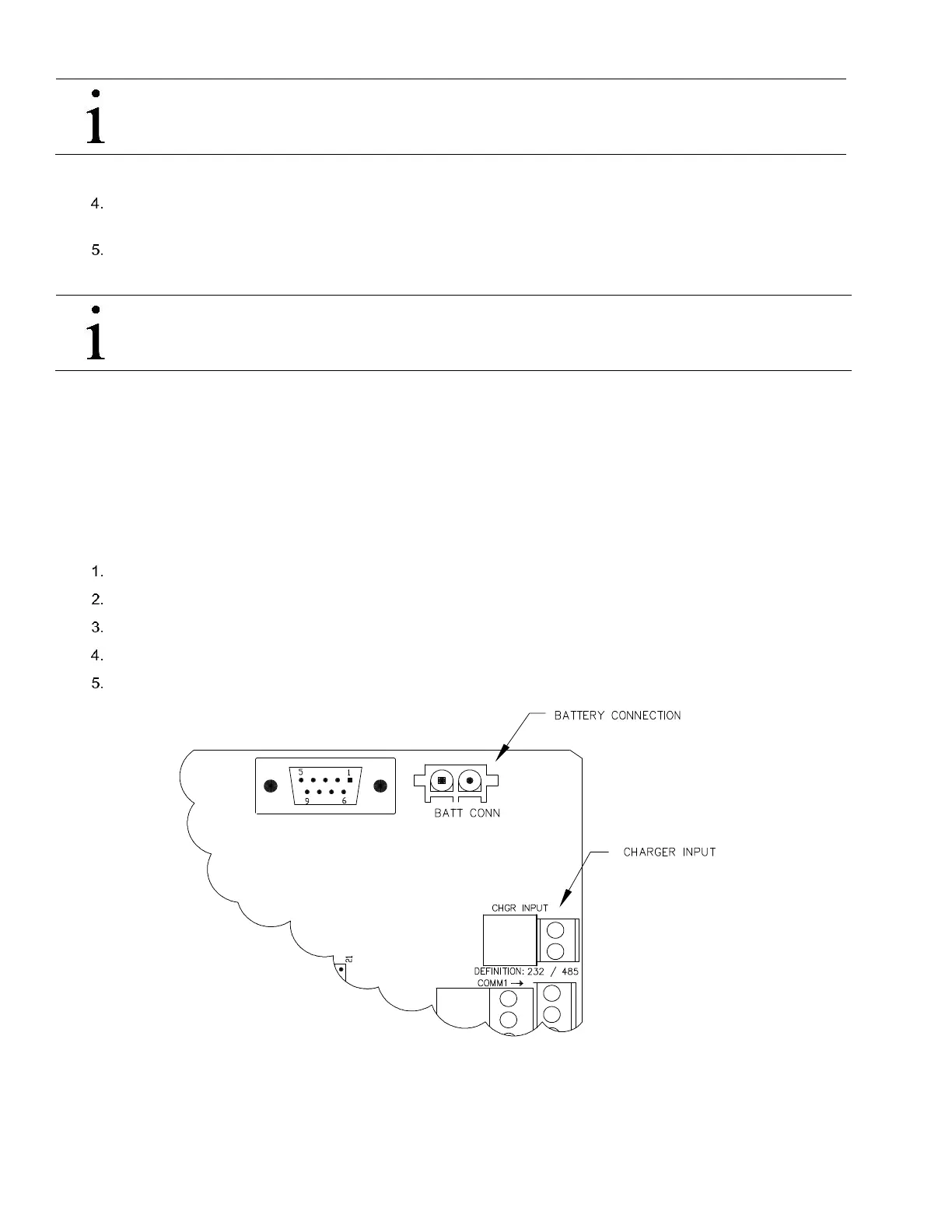
Connect the battery pack connector to the digital board battery connection J1 connector (see Figure 53).
Replace battery pack cover.
Observe the LCD, the display should be on and scrolling through the startup diagnostics sequence.
Figure 53 XFC
G4
Board Battery and Charger Input Connections
The battery pack is now installed.
 Loading...


