ABEM Terrameter LS
103
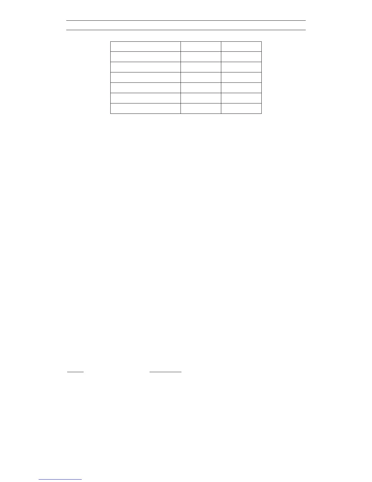
Pole-dipole 6 6
Schlumberger 7 10
Equatorial dipole-dipole 8 13
General surface array 11 11
Tomography 12 12
Potential 14 14
Multiple gradient array 15 15
If an array not defined in the list is to be used, array code 11 for general surface array
may be used. Alternatively array code 0 for resistance can be used, which means that
resistance instead of apparent resistivity is displayed during measurement. If array
code 12 is used only the electrode numbers, and not the coordinates are saved, which
is suitable for for instance measurements involving boreholes (see section on
geometry files below).
12.12 Geometry Files
The electrode coordinates for a borehole measurement are entered via a geometry file
(textfile with XYZ file extension), with the following format:
n-cables
Header cable 1
1 x
1,1
y
1,1
z
1,1
2 x
1,2
y
1,2
z
1,2
…
n
1
x
1,n1
y
1,n1
z
1,n1
Header cable 2
1 x
2,1
y
2,1
z
2,1
2 x
2,2
y
2,2
z
2,2
…
n
2
x
2,n2
y
2,n2
z
2,n2
Header cable 3
1 x
3,1
y
3,1
z
3,1
2 x
3,2
y
3,2
z
3,2
…
n
3
x
3,n3
y
3,n3
z
3,n3
12.13 Standard Spread Files
A number of standard spread files are supplied with Terrameter LS. It should be noted
that new files can be added and that the list may thus not be complete. The following
spreads are included with a standard firmware installation.
Name Description
2x21 Set of 2 electrode cables with 21 take-outs each
2x32 increasing Set of 2 electrode cables with 32 take-outs each
2x32 mirrored Set of 2 electrode cables with 32 take-outs each
4x21 Set of 4 electrode cables with 21 take-outs each
4x16 Set of 4 electrode cables with 16 take-outs each