ABEM Terrameter LS
4
2 Overview of the Instrument
2.1 The Connector Panel
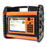
All connectors except external power are situated on the right side panel of the
Terrameter LS (Figure 3).
Figure 3. The Connector panel of Terrameter LS
The connectors:
Label Function
USB Connection of USB memory sticks, keyboard, external GPS etc.
Electrode 1-32 32-pole connector for electrode cables (1/2)
Electrode 33-64 32-pole connector for electrode cables (2/2) (not VES edition)
C1, C2 Banana plug connection for current electrodes (for instance for test
or connection of remote electrode)
P1, P2 Banana plug connection for channel 1 potential electrodes (for
instance for test or connection of remote electrode)