| Installation – Commissioning the wallbox
22
NOTE
Illustration of initialisation
The flash pattern illustrated above is only displayed on Controller wallboxes and on Extender wallboxes config-
ured in stand-alone mode. Ordinary Extender wallboxes in a group installation, however, show the F4 error pat-
tern (see page47) until the Controller wallbox has been detected and communication has been set up between
Controller and Extender wallboxes.
WARNING!
Checking the RCCB and MCB
Should the LED not flash, check the RCCB and the MCB inside the Wallbox eMH3 and switch the pivot levers to
position I if necessary.
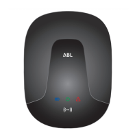
2 Measure the voltage at the RCCB terminals using
the voltage tester.
y In single phase installations, the voltage is
measured between the phase and neutral
conductors.
y In 3-phase systems, all phases are measured
against each other (400 V) and all phases are
measured against the neutral conductor (230 V).
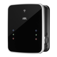
3 Replace the electronic components cover in the
housing and fix it into place with the screw you
removed in Step 8 of section "Preparing and fixing
the wallbox in place" on page17.
T
T
METER
M
E
T
E
R
C
N
T
R
L
CONTROL
CONTROL
METER
T
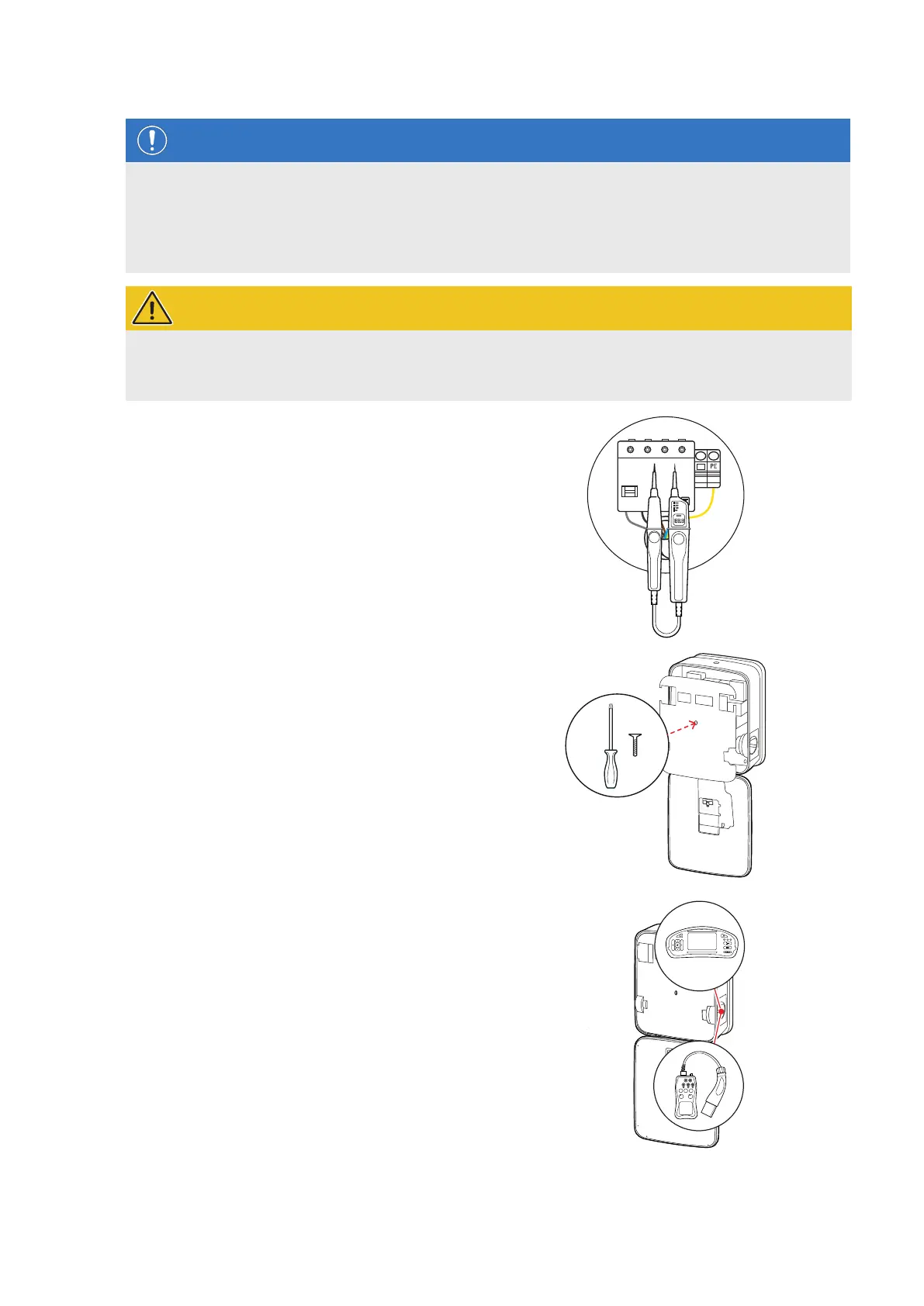
4 Use the installation tester and the vehicle simulation
adapter to conduct all other required checks.
T
T
T
N PE
L1 L2 L3
 Loading...