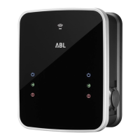
| Configuring the Wallbox eMH3 – Operation and address allocation in a group installation
30
Wallboxes are factory preconfigured with the following bus addresses:
Preconfiguration for Controller wallboxes
Charge controller Charge controller Energy meter Energy meter RFID LGW
L R L R
Twin 1 2 1 2 1 100
Single – 1 – 1 1 100
Preconfiguration for Extender wallboxes
Charge controller Charge controller Energy meter Energy meter RFID LGW
L R L R
Twin 3 4 3 4 3 102
Single – 3 – 3 3 102
NOTE
Basics of address allocation
Bus addresses in the system are allocated from wallbox to wallbox in ascending order.
The address for the Logging Gateway (LGW) is only relevant for calibration law compliant wallboxes.
Up to 16 unique bus addresses may be allocated.
The upper limit address value of 16 will not be reached in smaller systems.
The examples below show address allocation patterns for systems with Twin, and systems with Single wallboxes.
However, operating mixed systems is also possible.
Bus address allocation for a system with Twin wallboxes
Charge controller Charge controller Energy meter Energy meter RFID LGW
L R L R
Controller 1 2 1 2 1 100
Extender 1 3 4 3 4 3 102
Extender 2 5 6 5 6 5 104
Extender 3 7 8 7 8 7 106
Extender 4 9 10 9 10 9 108
Extender 5 11 12 11 12 11 110
Extender 6 13 14 13 14 13 112
Extender 7 15 16* 15 16* 15 114
*The upper limit address value of 16 has been reached.
Bus address allocation for a system with Single wallboxes
Charge controller Charge controller Energy meter Energy meter RFID LGW
L R L R
Controller – 1 – 1 1 100
Extender 1 – 2 – 2 2 101
Extender 2 – 3 – 3 3 102
Extender 3 – 4 – 4 4 103
Extender 4 – 5 – 5 5 104
Extender 5 – 6 – 6 6 105

 Loading...