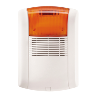
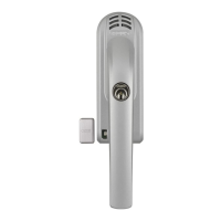
FUSG35000 siren
The siren is suitable for indoor and outdoor use. For further information, please refer to the safety
instructions relating to installation location and operating environment.
General installation instructions
Warning
The tamper contact may be triggered when installing the siren. In this event, the siren is
set to "LED" by default. If you have already configured the siren as "Siren" or "LED and
siren", please reset this to "LED" before installation. Otherwise, if for instance the siren's
alarm tone is suddenly triggered when carrying out an installation at a great height, this
could lead to a serious accident and physical injury or damage.
Alternatively, you can activate maintenance mode in order to avoid false alarms. See
chapter 5 ("Configuration").
When testing the siren's acoustic alarm tone, always maintain a minimum distance of 3 m
in order to avoid physical damage (e.g. to hearing).
The siren is only suitable for use in protected outdoor areas (IP44).
Ensure that the siren is installed within hand's reach (minimum 3 m installation height).
When choosing the installation location, ensure that the siren can be seen and heard from a long
distance.
Pressing the tamper contact for the first time activates the tamper contact. After this, if the tamper
contact is triggered, the tamper alarm is triggered.
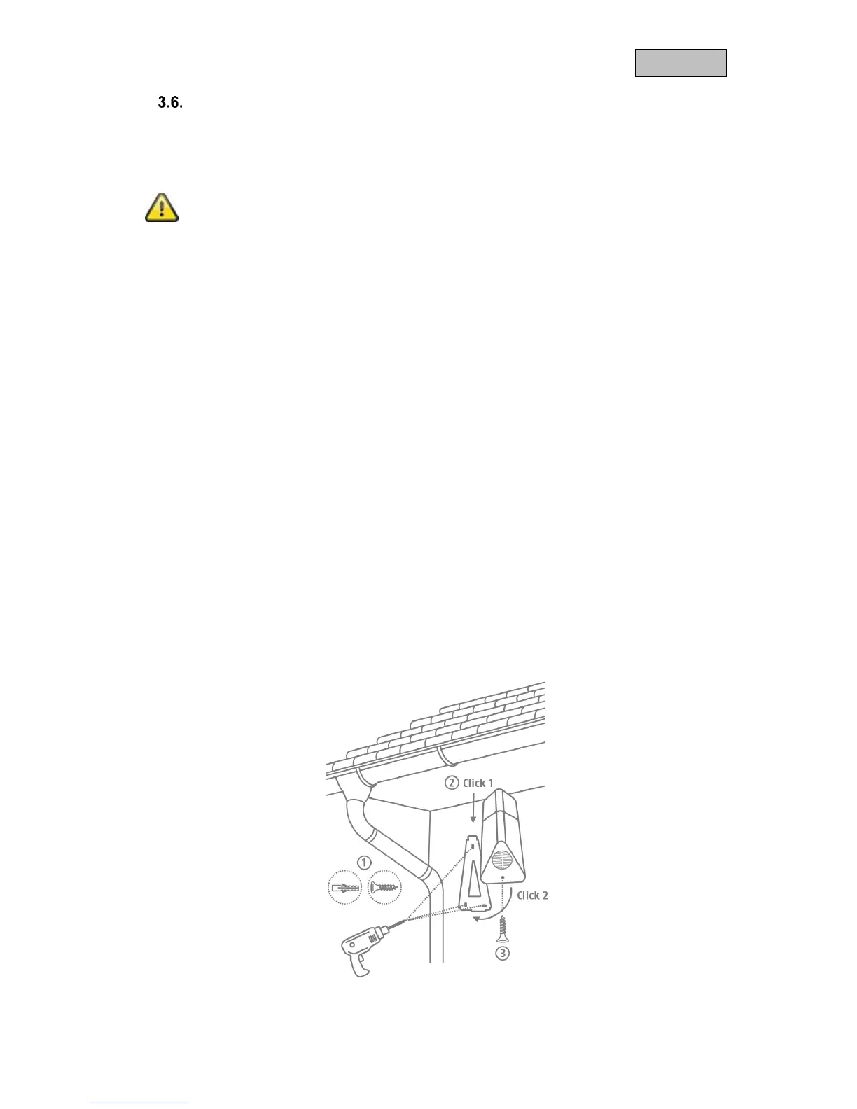
Drill installation
1. Stick the motion detector's drilling template in the desired installation location. Use a spirit level to
ensure the drilling template is straight. Drill holes in the specified positions and insert the screw
anchors provided. Remove the drilling template.
Attach the A-shaped bracket to the wall using the screws.
2. Connect the power supply unit provided to the siren and hook the sirens into the bracket from
above (click 1), then press it against the wall (click 2).
3. Now tighten the small screw on the underside of the bracket.