42
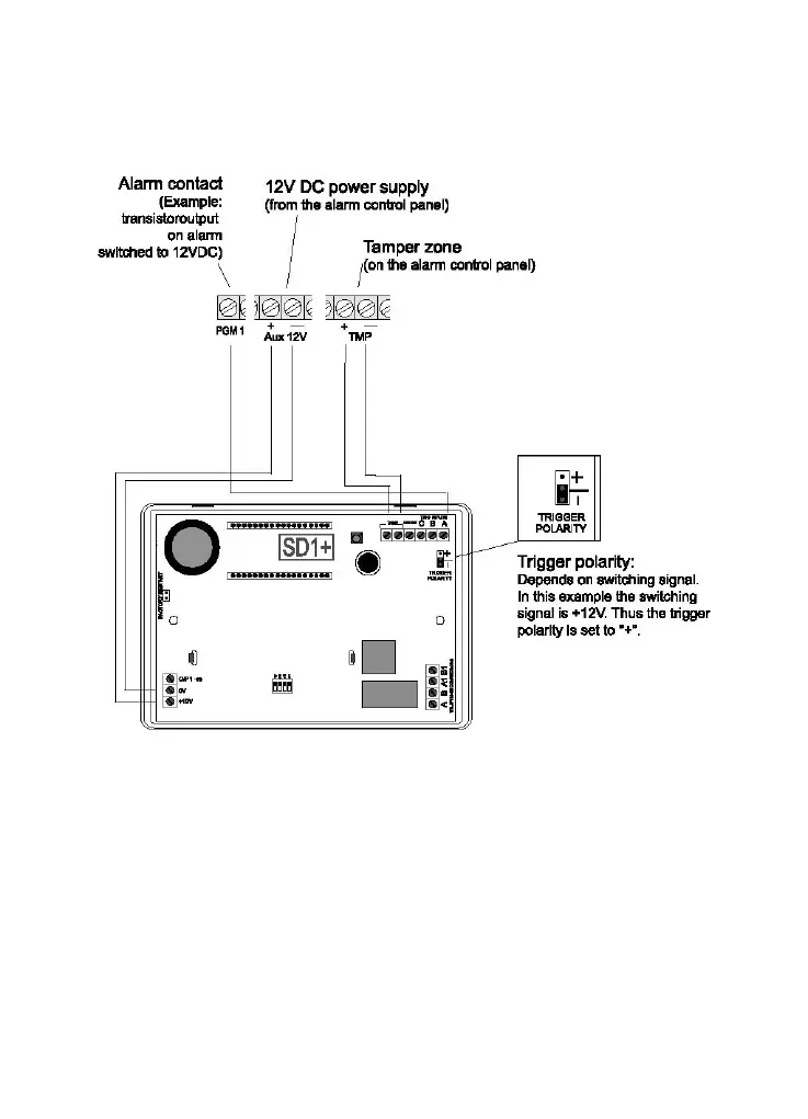
7.3 Wiring example
Various events can be assigned to the programmable switch outputs,
depending on the alarm centre used. Normally, these outputs should
be programmed to “Alarm” when switching with the Terxon PSTN
dialer. Pay attention to the correct polarity of the switch outputs.
If the siren output of the alarm centre is also used to trigger the dialer,
then the siren may emit noises from time to time. This can be
prevented with the help of a 1 KΩ resistance between the trigger input
and the +12 V input of the Terxon PSTN dialer.