130
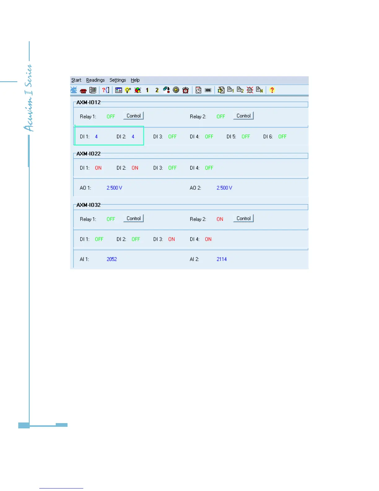
Fig 5-17 recorded number of pulses read by the utility software
Parameter Settings for Counting Input Pulses:
Take AXM-IO11 (AXM-IO1 module in logic NO.1) for example.
1. “109EH” register: if the bit is set as “1”, the counterpart digital input circuit is
set to be a counter of input pulses.
2. “109FH” register: this register is an unsigned integer. If this register is A , and
the digital input circuit is set to be a pulse counter, then the real number of
pulses counted by this DI circuit will be as follows:

 Loading...