132
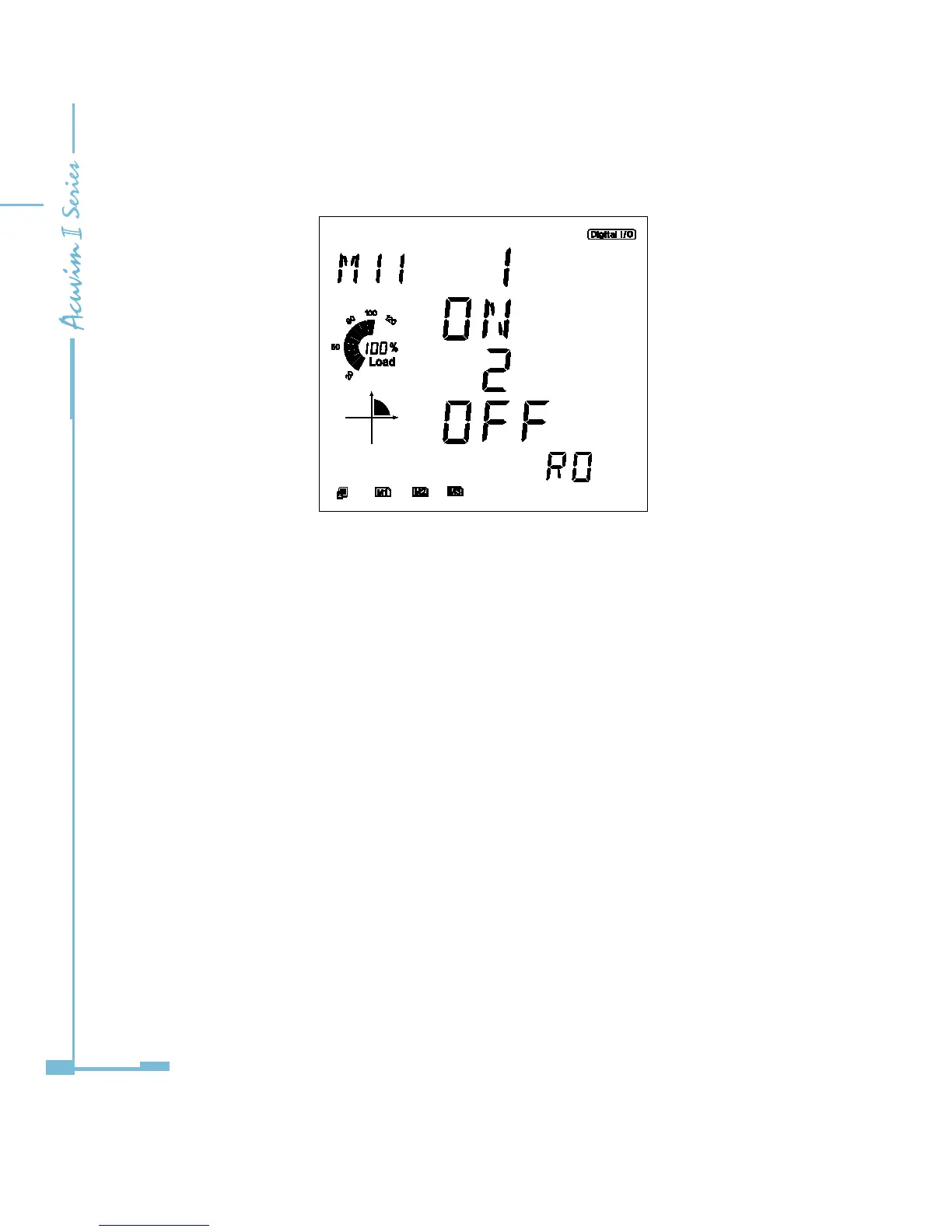
Fig 5-18 status of relays read on screen
b. Parameter Setting
Take AXM-IO11 (AXM-IO1 module in logic NO.1) for example.
“RO working mode (10A0H)” register: this register determines the working
mode of relays. If the register is “0”, then RO1 and RO2 will work in controlling
mode. If the register is “1”, then RO1 and RO2 will work in alarm mode.
“RO output mode (10A1H)” register: this register determines the output mode
of relays. If the register is “0”, then RO1 and RO2 will work in latching output
mode. If the register is “1”, then RO1 and RO2 will work in pulse output mode.
“RO pulse width (10A2H)” register: when the relays are working in pulse
mode, this register determines the period of time which can be set from 50
to 3000ms. For example, if this register is “100”, the relay (RO1 or RO2) will be
switched on for 100ms after receiving ON instruction and then be switched o.
The parameter setting is shown in Fig 5-15.

 Loading...


