185
5.3.5 Denition of DP Interface
The PROFIBUS module uses standard 9-pin D-type connector to access
PROFIBUS network. The mechanical and electrical characteristics of connector
are consistent with the requirements of IEC 807-3. The connector of PROFIBUS
is a socket, and the counterpart connector of cable is a plug. Connector pins are
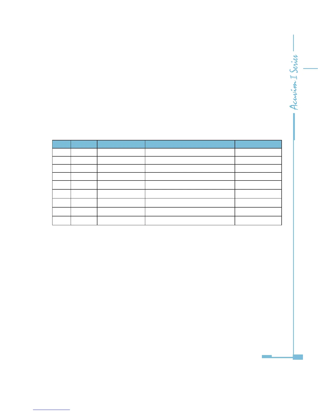
distributed as follows:
Table 5-16
*Note: Pin 4 is used for RTS controlling and TTL, which is optional.
5.3.6 Cable
Shielded twisted pair cable is recommended as reference to the EIA RS-485
standard. If the interference is within the EIA RS-485 standard then non-
shielded twisted pair cable can may be used.
5.3.7 Bus Terminal
Based on DP standard, the first station and the last station in PROFIBUS-DP
network should connect bus terminal (resistor), and it is not necessary for other
stations, as shown in the gure below.
Pins RS-485 ID Content Used by PROFIBUS
1 —— SHIELD Power GND NO
2 —— N24V -24V Output NO
3 B RXD/TXD-P Data P (Receive /Send) YES
4 —— CNTR-P Controlling P YES
5 C DGND Digital Ground YES
6 —— Vp Positive Voltage YES
7 —— P24V +24V output NO
8 A RXD/TXD-N Data N (Receive /Send) YES
9 —— CNTR-N Controlling N NO
*

 Loading...


