190
Response
Below is the response that a slave device would send to a master.
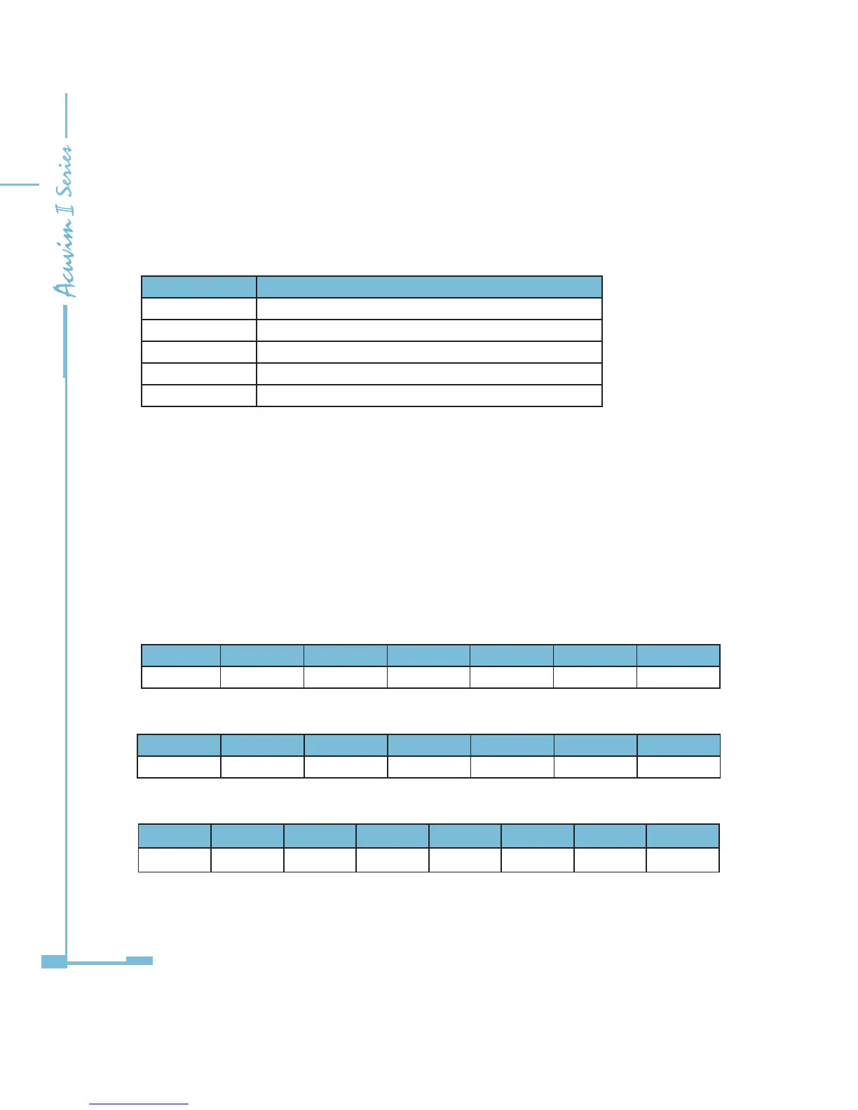
Table 5-18
Frame Bytes Caption
Byte1 The channel of inquiry frame
Byte2 01H
Byte3 byte count
Byte4 coil status
Byte5~32 0
The coils in the response message are packed as one coil per bit of the data eld.
Status is indicated as 1=ON and 0=OFF. The LSB of the rst data byte contains
the output addressed in the query. The other coils follow toward the high order
end of this byte, and form low order to high order in subsequent bytes.
Example: reading Relay1 and Relay2 status (start register address is 0000H). Use
4 channels.
Table 5-19
Query
Byte1 Byte2 Byte3 Byte4 Byte5 Byte6 Byte7~32
04H 01H 00H 00H 00H 02H 00H
Response
Byte1 Byte2 Byte3 Byte4 Byte5 Byte6 Byte7~32
04H 01H 01H 02H 00H 00H 00H
Coil Status
7 6 5 4 3 2 1 0
0 0 0 0 0 0 1 0
MSB LSB
( Relay 1 = OFF, Relay 2=ON )

 Loading...


