18
proximity to the equipment, within easy reach of the operator, and shall be
marked as the disconnecting device for the equipment.
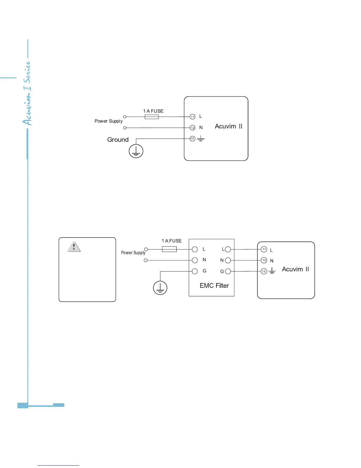
Fig 2-7 Power supply
A fuse (typical 1A/250Vac) should be used in the auxillary power supply loop.
No.13 terminal must be connected to the ground terminal of the switchgear. An
isolated transformer or EMC lter should be used in the control power supply
loop if there is a power quality problem in the power supply.
Fig 2-8 Power supply With EMC lter
Choice of wire of power supply is AWG22-16 or 0.6-1.5mm
2
.
Voltage Input
Maximum input voltage for the Acuvim II series meter shall not exceed
400LN/690LL VAC rms for three phase or 400LN VAC rms for single phase.
Potential Transformer (PT) must be used for high voltage systems. Typical
secondary output for PTs shall be 100V or 120V. Please make sure to select an
NOTE
A lter should be
used if there is an
EMI problem.

 Loading...


