64
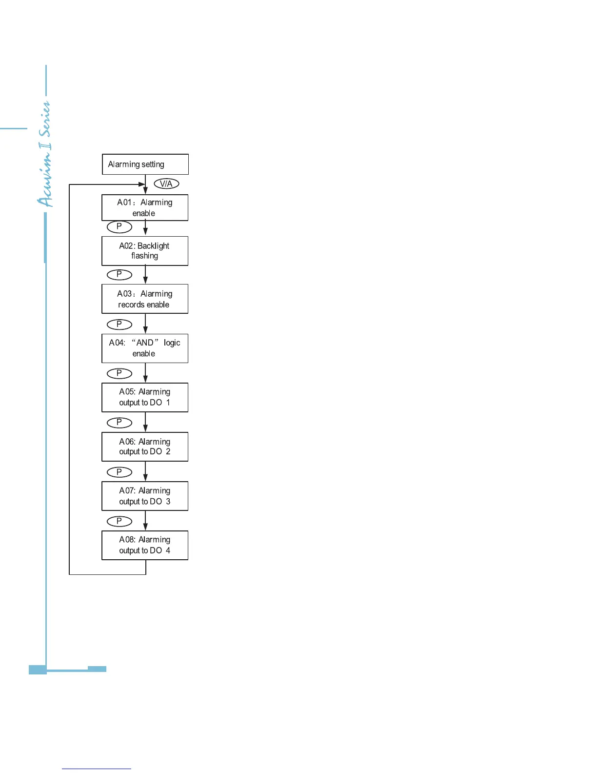
Yes: Alarm enable; No: Alarm disable
It can be selected as cue signal for alarming.
Yes: backlight ashes upon alarm condition; No: no backlight ashing
There are 16 alarm channels available. Each channel is controlled and enabled
1 bit each from a 16-bit register. Bit value of 1 means that the corresponding
alarm channel is enabled whereas 0 means that the channel is disabled. The
meter will display the value of this 16-bit register in decimal numbers (for
dierent channel combination). For example, 00000 means that all channels
are disabled; 00001 means only the rst channel is enabled; 65535 means that
all channels are enabled. Refer to section 4.4 on page 65 for more details.
"AND" logic relationship can be set among channels. When an "AND" logic is in
place, both channels have to be triggered before the meter sends out the
alarm signal. The logic can be set according to the predened rule (refer to
section 4.4 for more details). User can setup up to 8 logic relationships for
alarming. Each logic relationship is controlled and enabled 1 bit each from
a 16-bit register (only the lower 8 bits are used). Bit value of 1 means that
the corresponding logic relationship is enabled whereas 0 means that the
relationship is disabled. The meter will display this 8-bit value in decimal
numbers (for dierent relationship combination). For example, 000 means that
all relationships are disabled; 001 means only the rst relationship is enabled;
255 means that all relationships are enabled.
When DO1 works in alarming mode, a 16-bit register is used to control which
channels are associated with this output. Similar to the alarm channel
selection,this 16-bit value is expressed in decimal when reading on the meter
front. For example, 00000 means that no alarm channels are associated to this
output; 00001 means that alarm channel 1 is associated to DO1; 65535 means
that all alarm channels are associated to DO1. Refer to section 4.4 for more
details.
If 2 AXM-IO2 modules are attached to the meter, DO1 and DO2 denote to the
rst and the second DO channel of AXM-IO21; DO3 and DO4 denote to the rst
and the second DO channel of AXMIO22 respectively. DO2, DO3 and DO4 use
the same setup method as DO1.

 Loading...


