6-8 TUNING THE CONTROL LOOPS
SB1391 Hardware and Setup Guide - Document revision no. 1.14
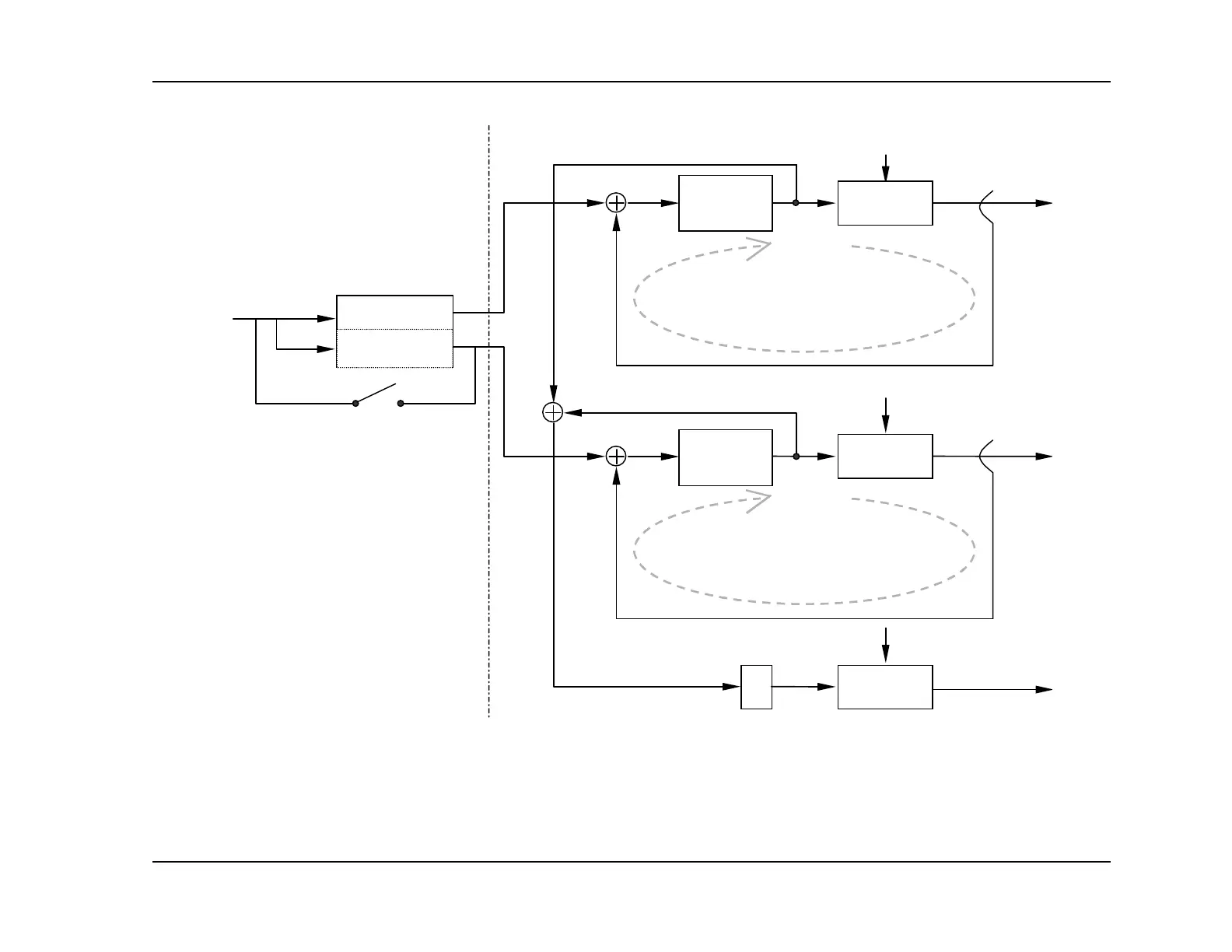
sin (CP)
Sin (CP + 120º)
+
I
c
(current
command)
Motor phase T current
+
Pulse width
modulation
Motor phase S current
-
-
I
Tc
I
Sc
CURRENT
LOOP
CURRENT
LOOP
Vbus
Pulse width
modulation
+
Vbus
+
Pulse width
modulation
-1
Vbus
Motor phase R current
T
S
R
Current filter
D3, D4
Fi
. 1-4
Current filter
D3, D4
Fi
. 1-4
Motor
terminal
mplifier stageCommutation stage
For DC brush motor: S1 closed, motor
connected between R and S
S1
FIGURE 6-3 Commutation and power amplifier stage