MOUNTING AND WIRING 4-5
SB1391 Hardware and Setup Guide - Document revision no. 1.14
4.3. Power Connectors
Warning
Do not turn on the power while making connections. Doing so could result in
severe bodily injury or damage to the unit.
TABLE 4-3 Power connectors
Power Connectors
Drive Supply
Control
Motor
Fan 24Vdc
Regen (external regeneration resistor)
Power Supply
Warning
Do not solder wires before insertion into the connector. Solder will contract
and cause a loose connection over time.
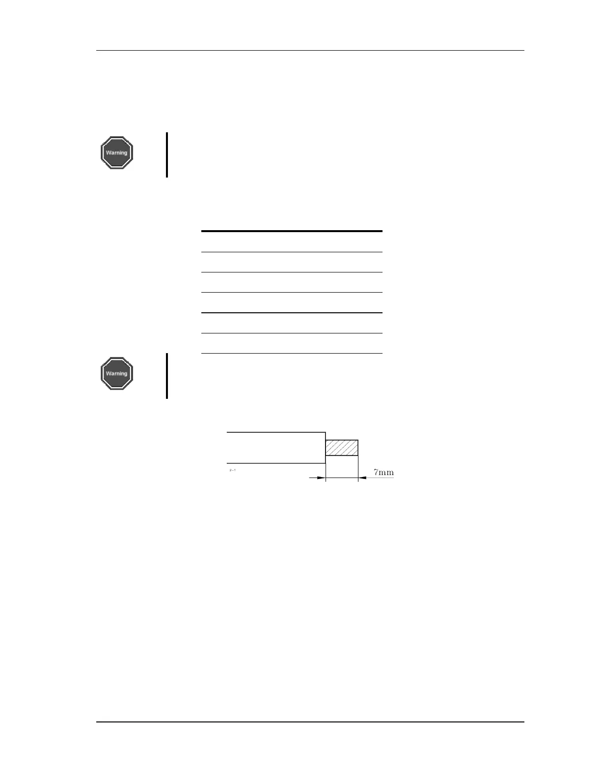
Wire should be stripped 7mm (as shown in FIGURE 4-3).
FIGURE 4-3 Wire stripping dimension for terminal block connections
4.3.1. Drive Supply and Control Supply Connectors
The supply to the drive power section is separate from the supply to the control section. This
separation makes it possible to maintain position information, communication, and ACSPL
program execution in the event that power must be removed for safety reasons.