4-14 MOUNTING AND WIRING
SB1391 Hardware and Setup Guide - Document revision no. 1.14
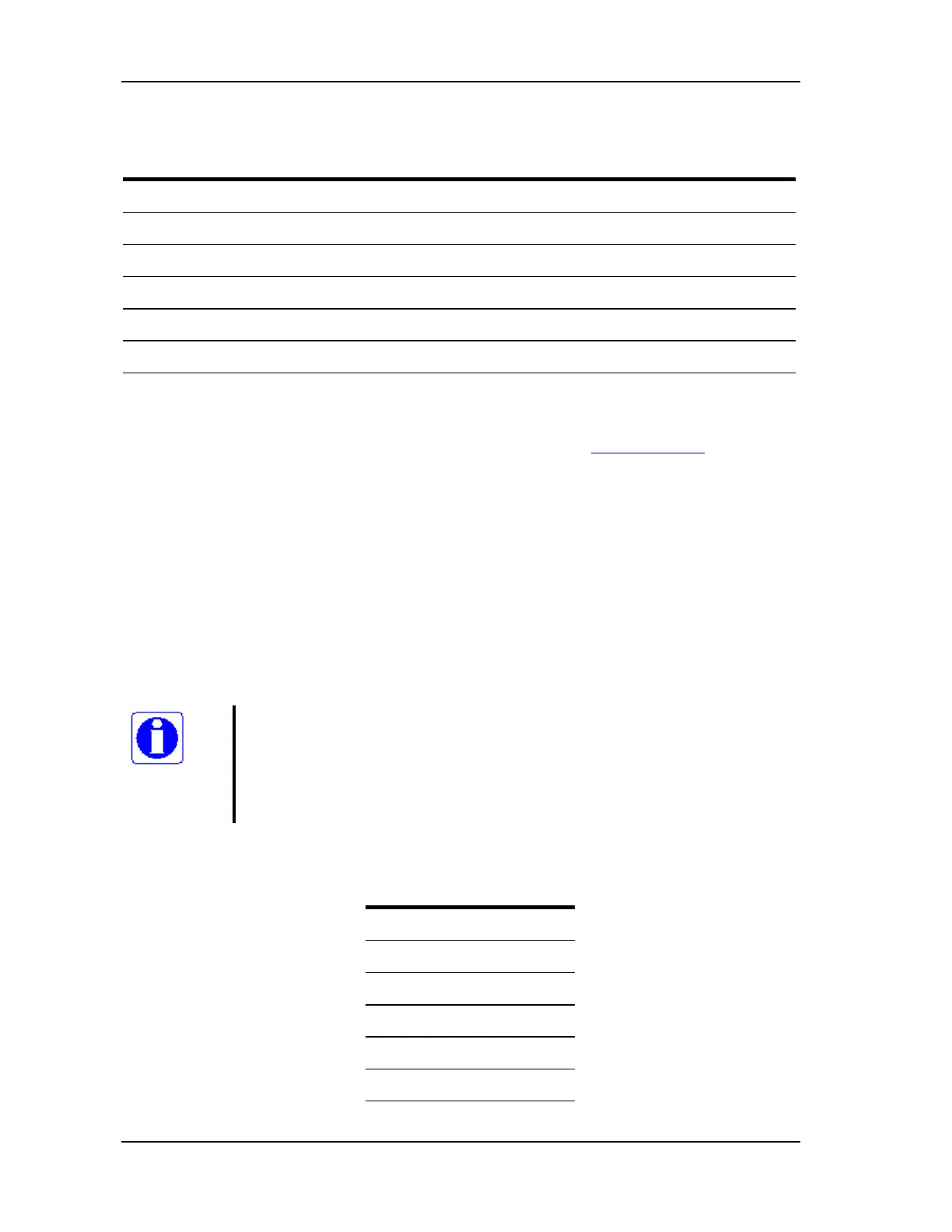
TABLE 4-12 Fuse replacement procedure
Step Name
1. Power off the control module.
2. Remove fuse holder (threaded cap located on top of the control module).
3. Remove old fuse from fuse holder. Old fuse can be discarded.
4. Insert new fuse into fuse holder.
5. Insert fuse holder into control module and thread into place.
6. Power on the control module.
4.3.4. Fan 24Vdc Connector (J10)
The Fan 24 Vdc is a header plug-in connector manufactured by Phoenix Contact, part no.
MC 1,5/2-GF-3,81. It receives plug part number MC 1,5/2-STF-3,5.
Use 24 to 18 AWG wire for the Fan connector.
When the ambient temperature is above 25
o
C and the control module is operated at full power,
the heat sink temperature can reach 75
o
C, which will shut off the power stage. To prevent this,
forced air cooling is required.
It is recommended to use a 24 Vdc fan, which can be supplied from this connector. The fan wires
should be 24 to 18 AWG.
4.4. Control Connectors
Further information
An overview of ACSPL parameters for programming the hardware interface
(serial connection, I/O, display, etc.) can be found in Chapter 6, "Hardware
Interface Parameters." More detailed information can be found in the ACS
Software Guide.
TABLE 4-13 Control connectors
Control Connectors
RS-232/422
CAN
Encoder 1+Hall / Resolver
Encoder 2
HSSI / PEG
I/O + Safety