MOUNTING AND WIRING 4-15
SB1391 Hardware and Setup Guide - Document revision no. 1.14
Use 24 to 20 AWG wire with the control connectors.
4.4.1. RS-232/422 Connector (J1)
The serial connector is D-type, 9 pin, male.
TABLE 4-14 Serial connector pins
Pin Name Description
1 SHIELD RS-232/422/485 shield
2 RX232 RS-232 receive signal
3 TX232 RS-232 transmit signal
4 5L +5Vdc supply
5 GND RS-232 ground
6 TX+ RS-422/485 positive transmit signal
7 TX- RS-422/485 negative transmit signal
8 RX+ RS-422/485 positive receive signal
9 RX- RS-422/485 negative receive signal
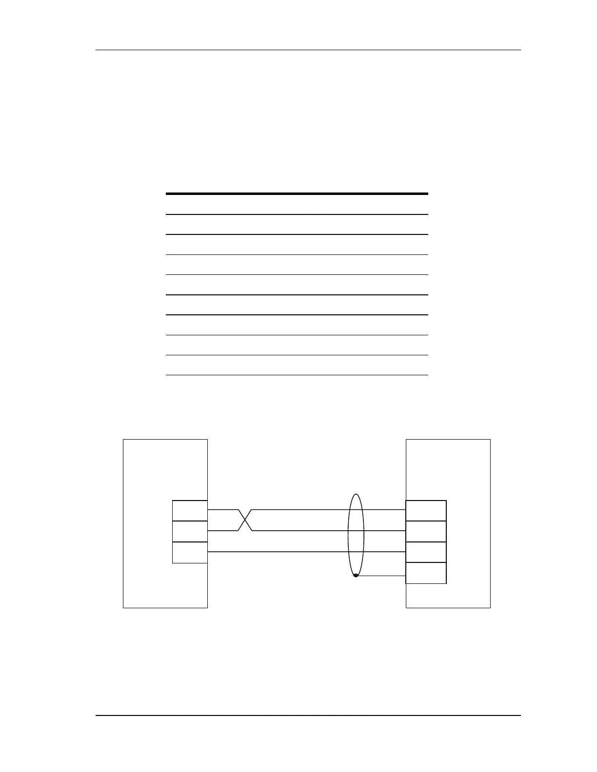
When making the serial connection, verify that the PC receive is wired to the control module
transmit and the PC transmit is wired to the control module receive.
FIGURE 4-13 RS-232 connection
PC
Rx
Tx
Gnd
RS-232
Control
Module
Rx
Tx
Gnd
Shield