4-16 MOUNTING AND WIRING
SB1391 Hardware and Setup Guide - Document revision no. 1.14
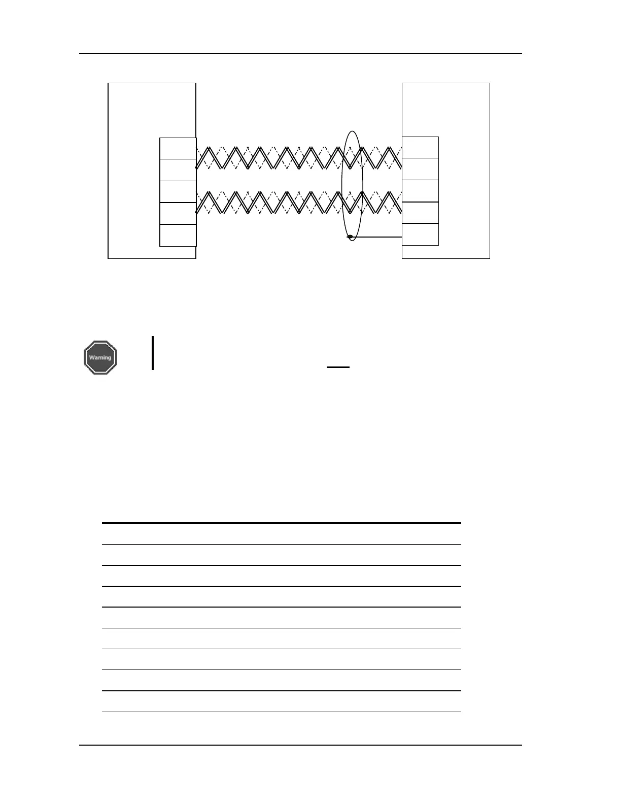
FIGURE 4-14 RS-422/485 connection
4.4.1.1. Partial Communications Shutdown
To prevent unauthorized interference with the operation of the controller, turn on the COM_SD
DIP switch on the front panel of the control module.
Warning
For CAN communication, COM_SD must
be OFF.
4.4.2.
CAN Connector
(J6)
The optional CAN bus connector is D-type, 9 pin, male.
The CAN support option must be specified in the product order.
Up to 127 devices can be connected on the same CAN line.
TABLE 4-15 CAN connector pins
Pin Name Description
1 NU Reserved
2 CANL CAN bus negative signal
3 CGND CAN bus supply ground
4 NU Reserved
5 SHIELD
Cable shield / screen
6 CGND CAN bus supply ground
7 CANH CAN bus positive signal
8 NU Reserved
9 VCAN+ CAN bus supply 9Vdc to 28Vdc
PC
Control
Module
RS-422/485
Rx+
Rx-
Tx+
Tx-
Gnd
Tx+
Tx-
Rx-
Rx+
Shield