6-18 TUNING THE CONTROL LOOPS
SB1391 Hardware and Setup Guide - Document revision no. 1.14
Action
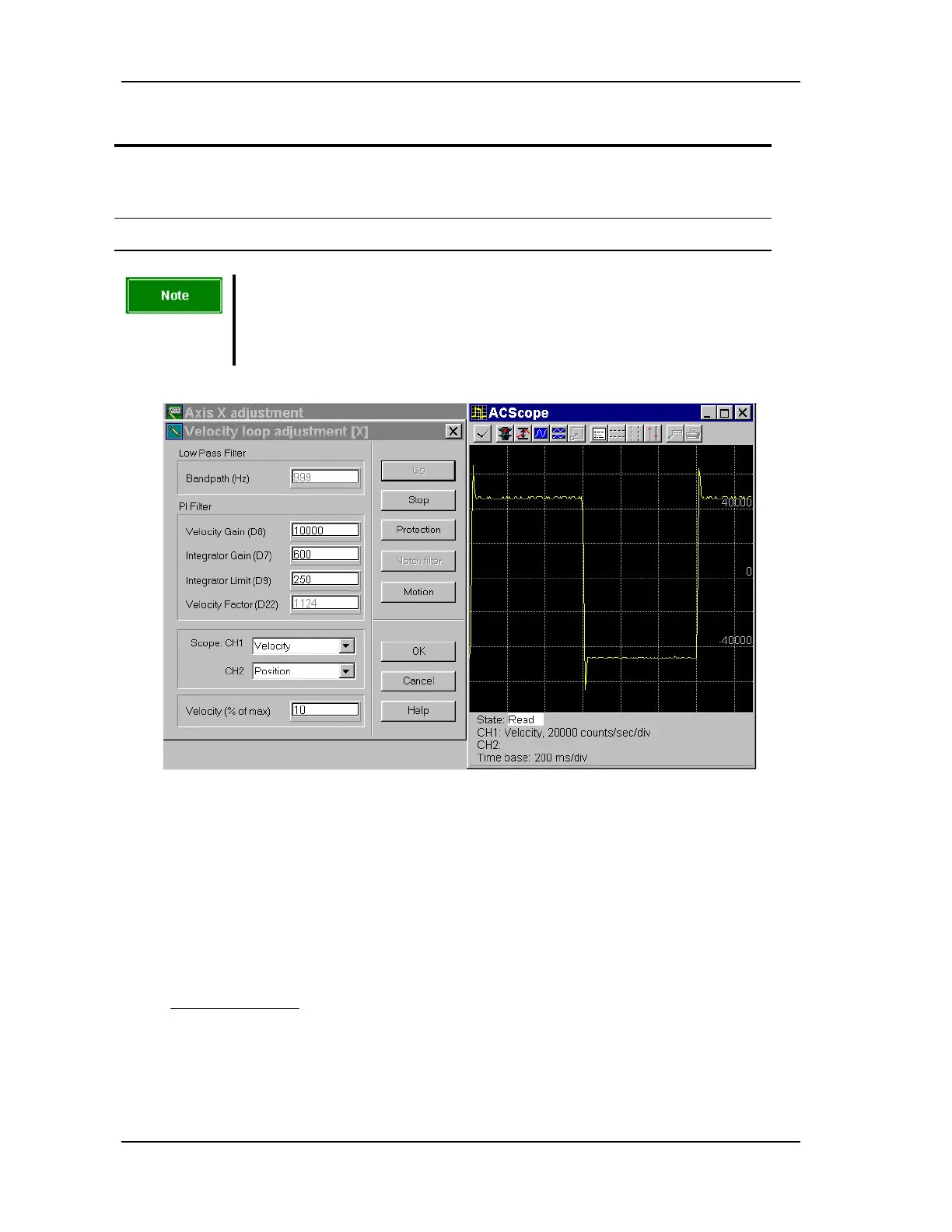
7. Change D9 (Integrator Limit), until the overshoot is about 10%. A good velocity loop
response is shown in FIGURE 6-11.
8. Click OK to complete the Velocity loop adjustment step.
Note
The Velocity loop adjustment step is also affected by the values of the
D5, D6, and D10 parameters. The parameters are accessible later, in
the Position loop adjustment step.
FIGURE 6-11 Velocity loop step response
6.6. Position Loop
The position filter is a pure proportional gain. It is set with the parameters GA and GF.
The gain value is
GF
GA
−
× 2 . (GF ranges from 0 to 8.)
The bandwidth of the position loop is:
14.3222
22000
××
××
−
D
GA
GF