TUNING THE CONTROL LOOPS 6-19
SB1391 Hardware and Setup Guide - Document revision no. 1.14
Note
It is recommended that the bandwidth of the position loop (f
pc
) be
approximately equal to
0
Gain)r (Integrato D7
2
.
6.6.1. Position Loop Tuning
Action
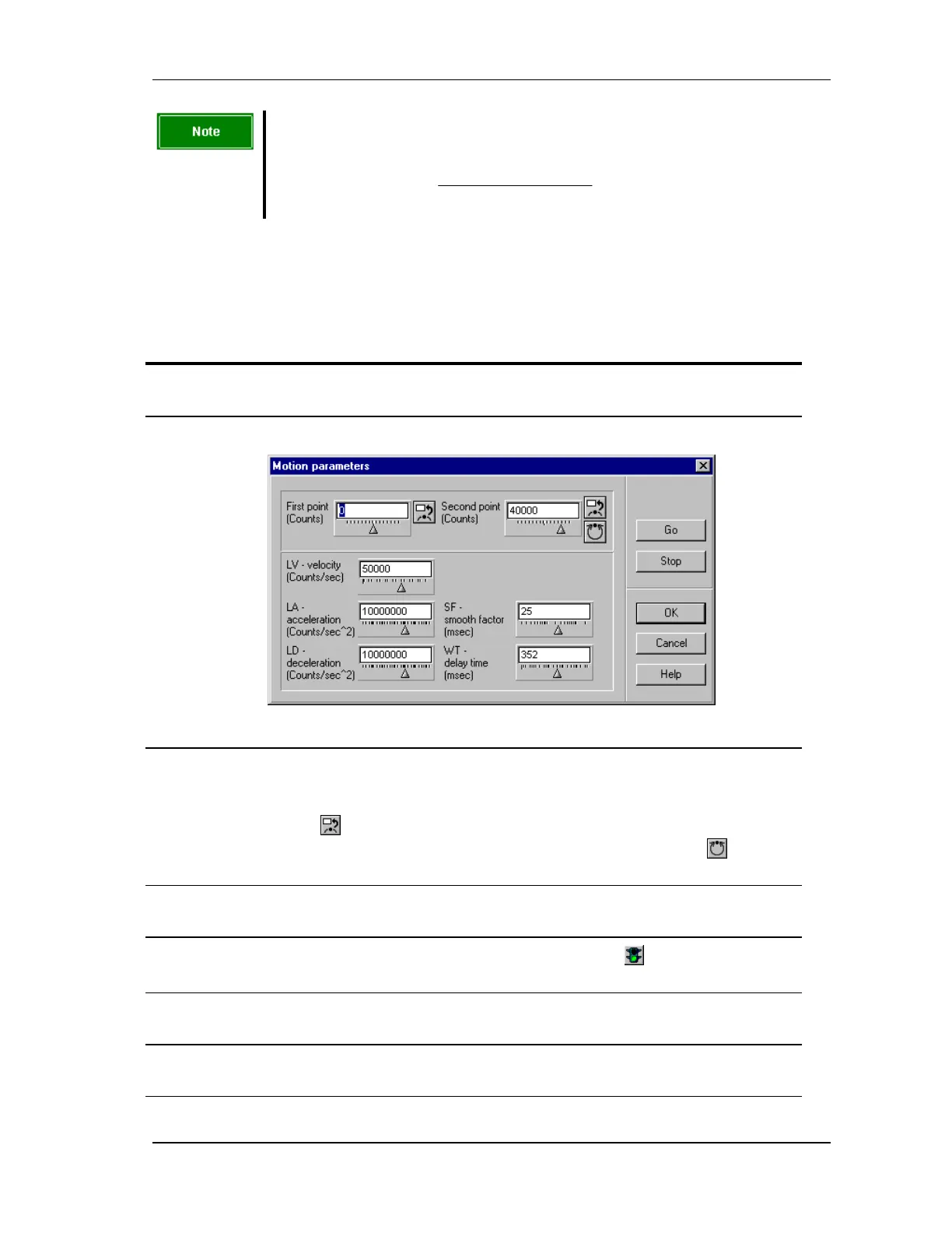
1. Click the Motion button to open the Motion parameters dialog box as shown in
FIGURE 6-12.
FIGURE 6-12 Motion parameters dialog box
2. Define the motion profile for the test by setting the First point and the Second
point. To set a point, either enter a number (corresponds to an absolute position of
the encoder) or move the motor axis to the desired position and click the Set From
Encoder button
to set the point directly to the value of the current encoder
reading. For the second point, there is also a Set One Revolution button , which
sets the second point exactly one full encoder revolution distant from the first point.
3. Set other motion parameters as necessary, and click OK to close the Motion
parameter dialog box.
4.
Click the start button in the Scope toolbar and the Go button in the Position loop
adjustment dialog box.
5. Set Dead Zone Min (D5), Dead Zone Max (D6), and Zero FF Zone (D10) to 0.
(These parameters are used only with piezoelectric motors.)
6. Set FN to zero. For a high friction load, increase FN (range 0 to 255) to overcome
friction.