4-32 MOUNTING AND WIRING
SB1391 Hardware and Setup Guide - Document revision no. 1.14
Pin Name Description
11. S_DATA1- HSSI data 1 input (inverted)
12. X_STA- X status output (inverted)
13. NC Not connected
14. X_PEG- X PEG output (inverted)
15. NC Not connected
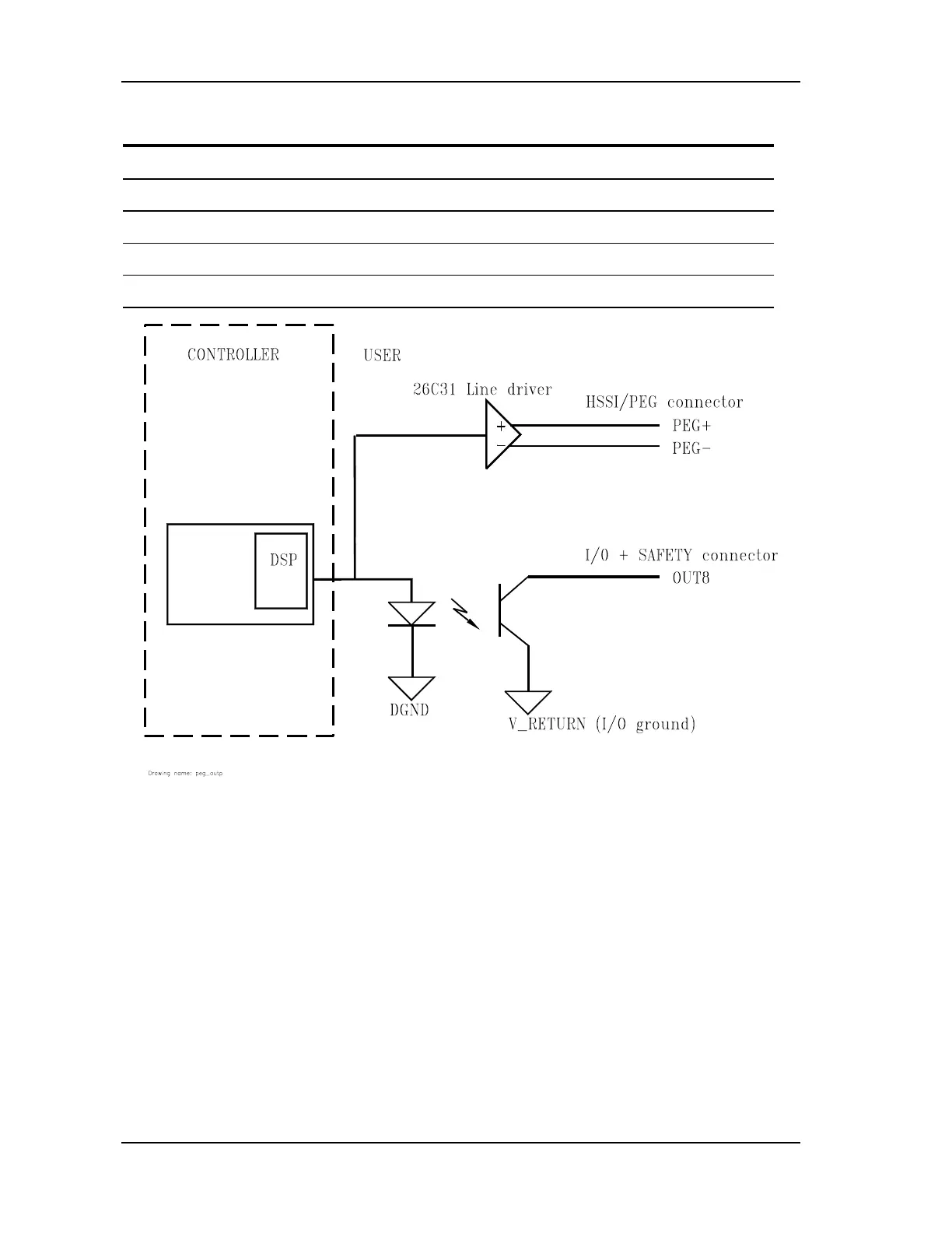
FIGURE 4-27 PEG outputs and corresponding digital outputs
4.5. Indicators, Switches, Display, and Test Points
4.5.1. Indicator LEDs
The locations of the indicator LEDs are shown in FIGURE 4-1.