TUNING THE CONTROL LOOPS 6-17
SB1391 Hardware and Setup Guide - Document revision no. 1.14
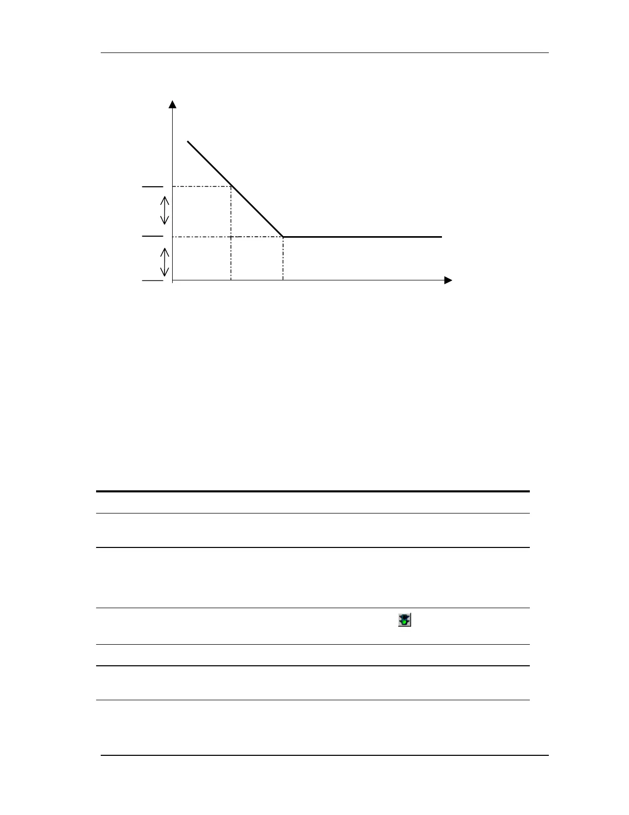
FIGURE 6-10 Velocity proportional-integral filter Bode diagram
6.5.2.1. Friction Compensation
The FN (Friction Number) parameter sets the initial value of the integrator in the velocity loop
(range is 0 to 255). Generally FN should be set to zero. For high friction load, increasing FN
shortens the start motion delay by compensating for the friction torque or force.
6.5.3. Velocity Loop Tuning
The velocity loop can be set in this step and fine tuned in the Position loop adjustment step.
Action
1. Set the Bandpath (bandwidth) of the Low pass filter at around 650 Hz.
2. If the motion system has high inertia and low resonance, it is useful to reduce the
Bandpath to between 100 Hz and 500 Hz.
3. Set D7 (Integral) to 0, D8 (Proportional Gain) to 1000, and set D9 (Integrator Limit)
to the value of TL (the maximum torque when the system is not accelerating). TL is set
in the Protection parameters step, which can be accessed directly from the Velocity
loop adjustment dialog box by clicking Protection.
4.
Click the start button in the Scope toolbar and the Go button in the Velocity loop
adjustment dialog box.
5. Double D8 until the response waveform approximates a square.
6. Increase D7 by hundreds until the overshoot starts increasing.
D7 should be between 240 (12Hz) and 2000 (100Hz).
20 log (amplitude)
(dB)
Frequency [Hz]
D7/2
20 dB
D8
D7/20