ACTpro 1500 and 1520 Operating and Installation Manual
Page 14
6.0 Hardware Installation Guide
6.1 Readers
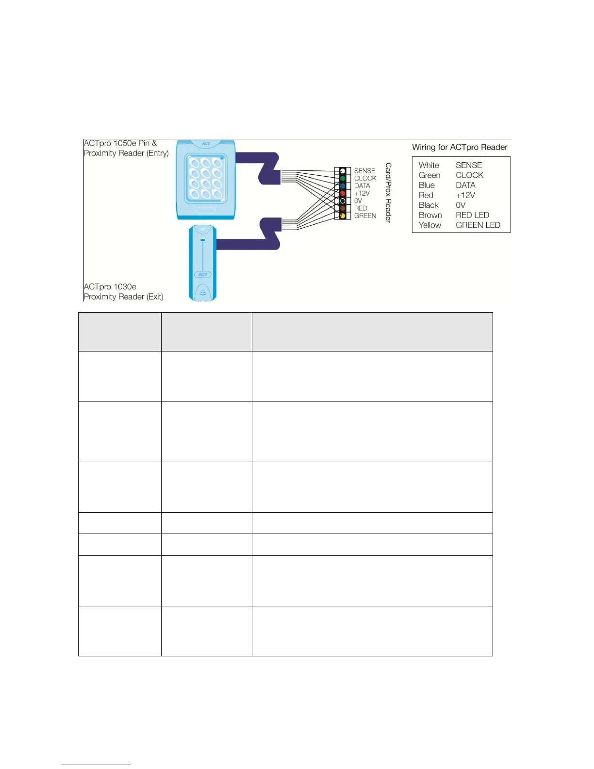
Diagram 7: Wiring of entry & exit readers.
Recommended
wiring colour
For Entry readers connect the reader SENSE cable or
terminal to the SENSE input pin.
For Exit readers, do not use this input.
This is the clock or strobe signal input on the ACTpro
1500.
Connect the reader CLOCK cable or terminal on the
reader to CLOCK input pin.
This is the Data input.
Connect the reader DATA cable or terminal on the
reader to DATA input pin
Positive +12V DC Supply voltage for the reader
0V Supply Voltage for the reader.
Red LED control output from the ACTpro 1500.
Connect the reader brown cable to the terminal marked
RED on the controller
Green LED control output from the ACTpro 1500.
Connect the reader green cable or terminal marked
GREEN on the ACTpro controller