7451A/7461A/7461P Digital Multimeter Operation Manual
6.5 Comparator Output
6-12
The calculation result signals of Hi, Go, and Lo are output to the signal output pins of HI, PASS, and LO.
The output to the PASS pin depends on the PASS conditions as shown in Table 6-3 and Table 6-4.
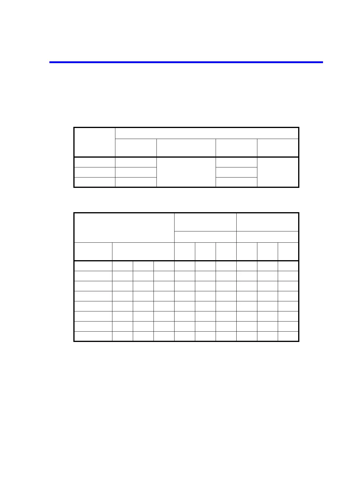
Table 6-3 Optical Semiconductor Relay Contact and TTL Logical Output (a)
Judgment result
Contact/TTL output pin
RELAY HI
RELAY PASS/TTL
PASS
RELAY LO TTL FAIL
Hi make
See Table 6-4
break
See Table 6-4Go break break
Lo break make
Table 6-4 Optical Semiconductor Relay Contact and TTL Logical Output (b)
PASS conditions
RELAY PASS
TTL PASS
TTL FAIL
Judgment result Judgment result
Panel setting
Remote Command
(ADC command)
Lo Go Hi Lo Go Hi
LGHLOP1MIP1HIP1LLLHHH
--H LOP0 MIP0 HIP1 H H L L L H
-G- LOP0 MIP1 HIP0 H L H L H L
L-- LOP1MIP0HIP0LHHHL L
L-H LOP1 MIP0 HIP1 L H L H L H
LG- LOP1MIP1HIP0LLHHHL
-GH LOP0 MIP1 HIP1 H L L L H H
--- LOP0 MIP0 HIP0 H H H L L L
H: break or Hi, L: make or Low