7451A/7461A/7461P Digital Multimeter Operation Manual
7.1.1 DC Voltage Measurement (DCV)
7-2
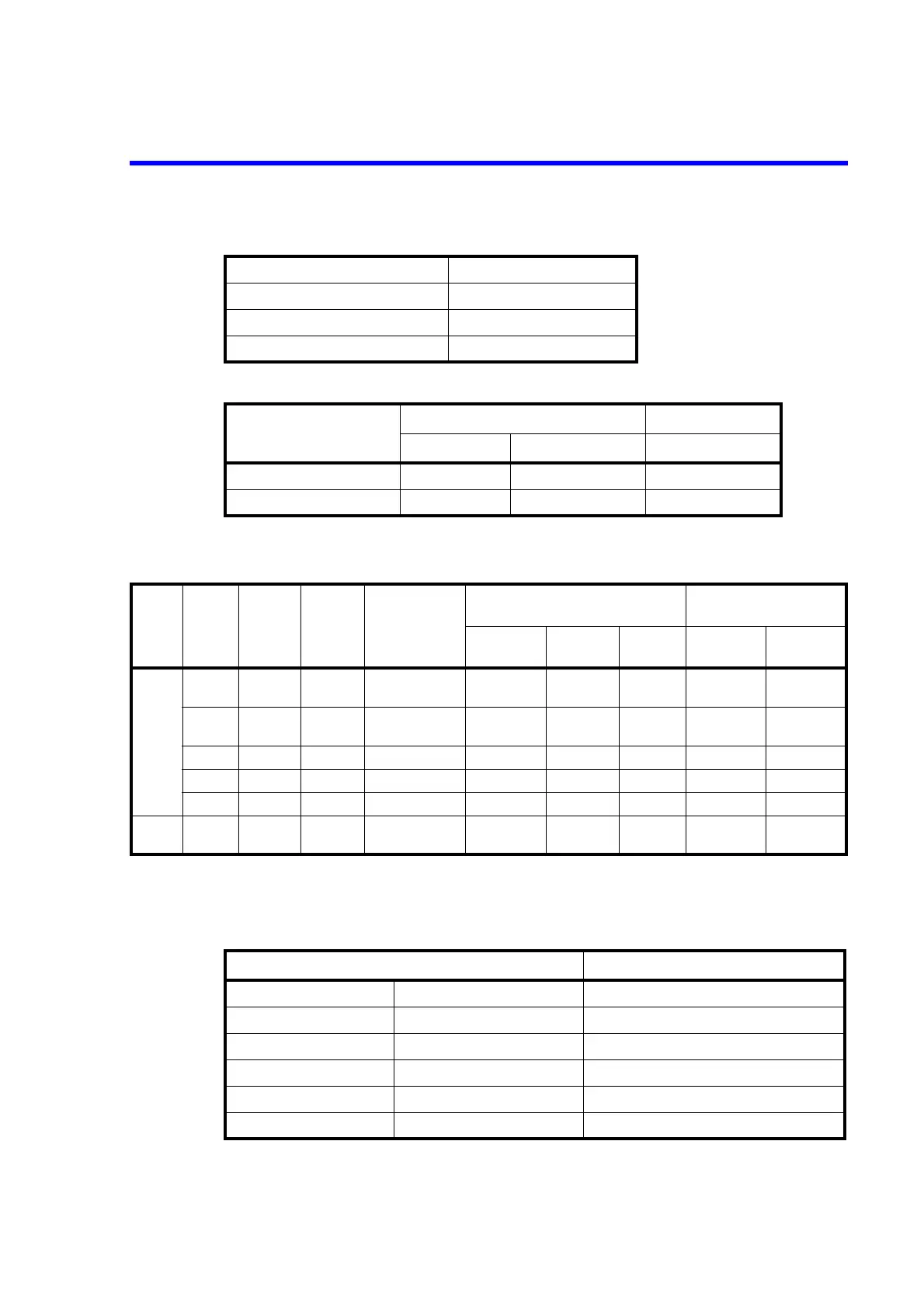
Maximum allowable applied voltage
Noise rejection ratio
• 7451A
Additional error depending on the integration time
Between V and COM 1000 Vpeak
Between BchHi and BchLo 200 Vpeak
Between BchHi, BchLo and COM 200 Vpeak
Between COM and the chassis 500 V
Integration time
Effective CMRR *4 NMRR
DC 50/60 Hz 0.08% 50/60 Hz 0.08%
Integral multiple of 1 PLC 130 dB 120 dB 60 dB
Others 130 dB 60 dB 0 dB
*4 Unbalanced impedance of 1 k
Input
terminal
Range
Maximum
display
Resolution
Input impedance
*3
Measurement accuracy *1
(% of reading + digits)
Temperature coefficient
(ppm of reading + digits)/C
24 hours
23C 1C *2
90 days
23C 5C
1 year
23C 5C
Auto-zero
ON
Auto-zero
OFF
V-COM 300 mV 319.999 1 V More than 1 G/
10 M1%
0.0020+5.0 0.0060+7.0 0.0140+7.0 8.0+1.0 8.0+5.0
3000 mV 3199.99 10 V More than 1 G/
10 M1%
0.0020+2.0 0.0060+3.0 0.0100+3.0 7.0+0.1 7.0+3.0
30 V 31.9999 100 V10 M1% 0.0020+3.0 0.0070+6.0 0.0150+6.0 8.0+1.0 8.0+3.0
300 V 319.999 1 mV 10 M1% 0.0020+2.0 0.0060+3.0 0.0140+3.0 8.0+0.1 8.0+3.0
1000 V 1099.99 10 mV 10 M1% 0.0020+2.0 0.0060+3.0 0.0140+3.0 8.0+0.1 8.0+1.2
BchHi-
COM
10 V 11.9999 100 V More than 1 G 0.0020+2.0 0.0100+3.0 0.0100+3.0 8.0+0.1 8.0+1.0
*1 Integration time: 10 PLC, Display digit: 5 1/2, Auto-zero: ON
*2 Relative value with respect to the calibration standard
*3 In the 300 mV and 3000 mV ranges, the input impedance can be selected from either 10 M or more than 1 G.
Integration time Additional error (digits + V)
100 s IT 200 s - In a 3 1/2-digit display 2+20
200 s < IT 2 ms Includes FAST1 and FAST2. In a 4 1/2-digit display 10+20
2.01 ms < IT < 9.99 ms - In a 5 1/2-digit display 20+20
10 ms <IT < 1 PLC - In a 5 1/2-digit display 2+20
1 PLC IT < 10 PLC Integral multiple of 1 PLC In a 5 1/2-digit display 1+0
10 PLC < IT 10 s Integral multiple of 1 PLC In a 5 1/2-digit display 2+0