Adept Lynx Platform User's Guide, Rev D
Page 60 of 126
Chapter 5: Connectivity
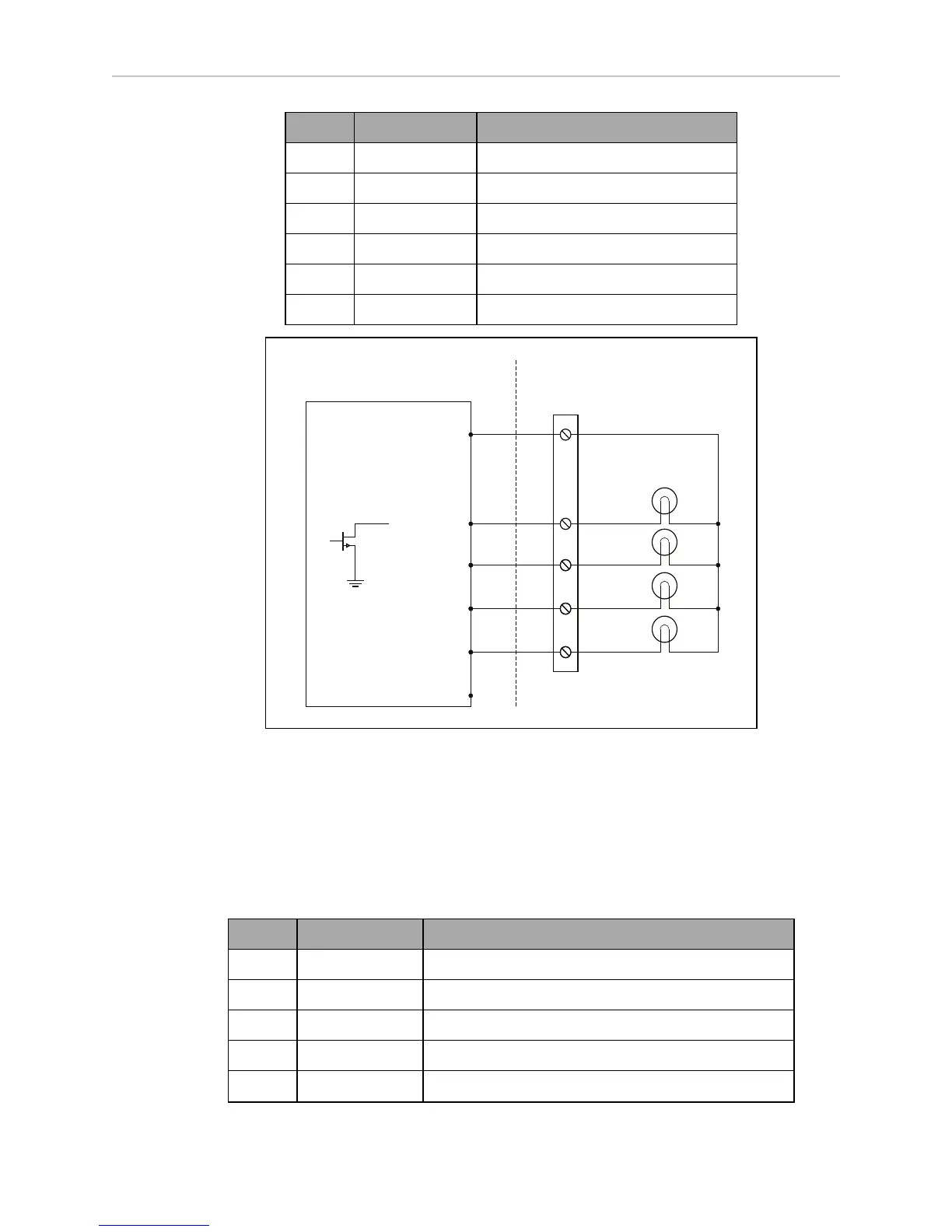
Pin No. Designation Notes
1 GND Cable shield
2 LIGHT_P1 Red
3 LIGHT_P2 Yellow or orange
4 VBAT_IO_OUT4 VBAT @ 0.5A Max (shared with DIO)
5 LIGHT_P3 Green
6 LIGHT_P4 Buzzer
VBAT_IO_OUT4
4
LIGHT_P1_N
2
LIGHT_P2_N
3
LIGHT_P3_N
5
LIGHT_P4_N
6
GND
1
(equivalent
circuit)
Typical user load
Wiring
terminal block
Adept-Supplied Equipment User-Supplied Equipment
Figure 5-6. Sample Light Pole Diagram
User Interface
Connector type Mini-Fit
®
7 x 2
Use Brake release, ON, OFF, E-Stop
Pin No. Designation Notes
1, 2, 3 FBAT_ALWAYS Fused VBAT @ 500 mA
4 ESTOP_USR_1L Short 4 & 11 to close ESTOP_USR_1
5 ESTOP_USR_2L Short 5 & 12 to close ESTOP_USR_2
6 ESTOP_OUT_1L Pins 6 & 13 short when ESTOP_CH1 is closed
7 ESTOP_OUT_2L Pins 7 & 14 short when ESTOP_CH2 is closed