EasyManuals Logo

Adtech DJ8849V2-A01 User Manual

Default Icon
133 pages
To Next Page IconTo Next Page
To Previous Page IconTo Previous Page
Page #116 background imageLoading...
Page #116 background image
User Manual of TV5600-B01 Series Dispensing Control System
116
andmodification
16
IN14
External reset, allow
configuration and
modification
16
IN31
17
IN15
External pause, system
configuration required
17
IN32
18
IN16
Universal input
18
IN33
-
-
Note: All the above input ports are universal input ports. To occupy the home and limit
ports, simply turn the home and limit configuration function of the corresponding
axis.
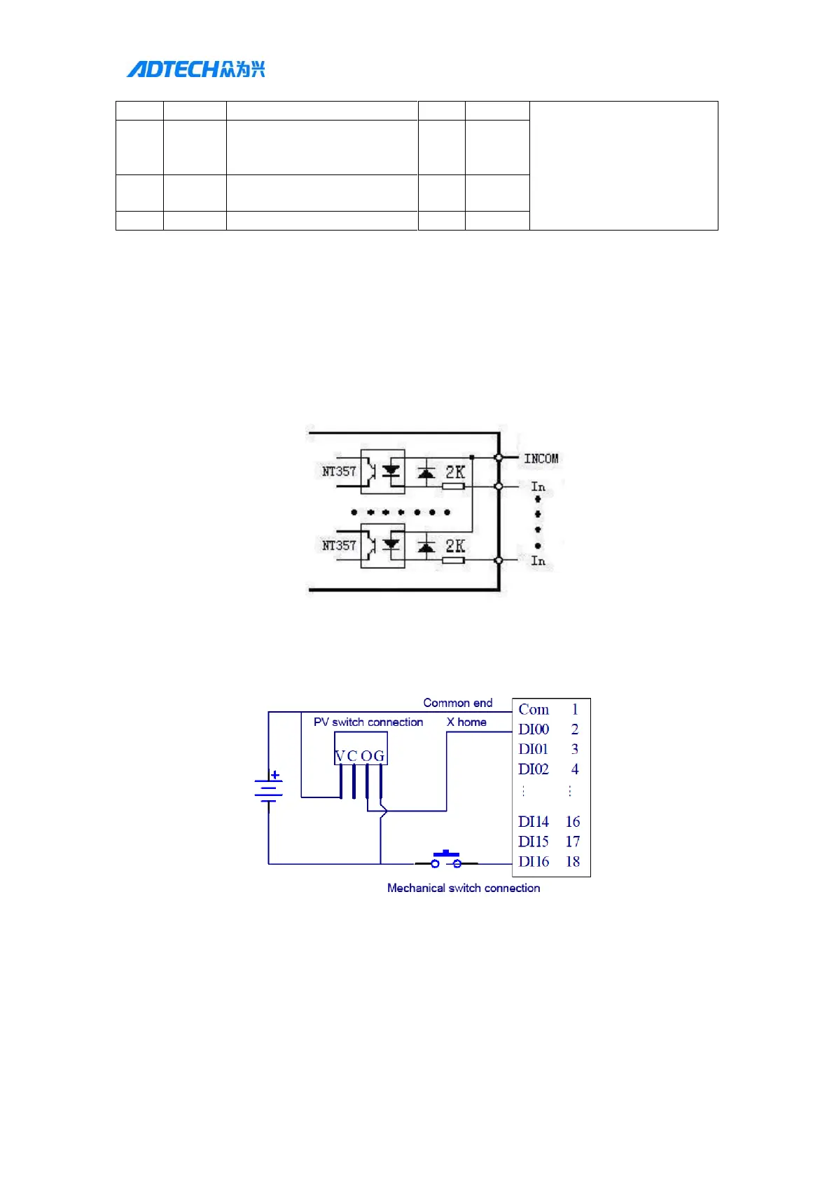
2. Input port wiring method
Controller internal input port diagram:
Controller general input connection: (PV switch V means VCC, G means GND, O means
output)
The INCOM terminal is connected to the positive terminal of the external power supply, and the
input signal is connected to the corresponding terminal pin. The common end of IN0-IN16 is
INCOM1; the common end of IN17-IN33 is INCOM2; when used, the common end needs to be
connected to +24V power supply, the input point is low level effective, and the current of single


Table of Contents

Questions and Answers:

Question and Answer IconNeed help?

Do you have a question about the Adtech DJ8849V2-A01 and is the answer not in the manual?

Adtech DJ8849V2-A01 Specifications

General IconGeneral
BrandAdtech
ModelDJ8849V2-A01
CategoryControl Systems
LanguageEnglish

Related product manuals