8 Meadowbank Road, Carrickfergus, BT38 8YF, Northern Ireland www.advancedsensors.co.uk
Page 15 of 93
OIW-HBO-0002-EX-005
OIW EX SERIES-SIDE STREAM
OPERATION MANUAL
Rev. 004 MAY 2015
2.3 – OVERVIEW OF MEASUREMENT AND MEASUREMENT CYCLE
2.3.1 – Measurement with the OIW Analyzer
Fluorescence is a commonly utilised method for measuring the oil content in water; however measurement accuracy is
dependent on oil droplet size. Variation in droplet size may significantly affect the measurement reading despite
consistent oil content. Uniformity of droplet size and distribution are required to achieve a reliable ‘calibrated’ reading.
Therefore all OIW EX Analyzers are equipped with an ultrasonic transducer that serves the following purposes:
1. Breaking down the oil droplets into a uniform size.
2. Emulsifying effect to uniformly distribute the oil droplets within the water sample.
3. Prevention of sensor head and measurement chamber contamination.
Measurements are taken for every second the analyzer cycle is started and the data recorded in the Syslog files.
Scheduled sample measurement readings will appear in blue while all other normal flowing readings will be displayed in
black and out of range values in red. The OIW-EX Series has two methods of graphically displaying measurements with
configurable phase times to optimize performance for a given oil type. Users must login to select the method, selectable
from the ‘Water Line Options’ menu under the ‘General Configurations’ tab, and configure the phase times, from the
‘Measurement Cycle’ menu under the ‘Schedule’ Configuration Options.
The following 2 measurement display options are available:
1. Trending: Real time display of data points as recorded are displayed in the Graphical Display panel with a
red trending line connecting data points for reference. A vertical blue line on the graph will indicate values
obtained during scheduled measurements. When Trending is NOT selected only the scheduled
measurements will appear on the graphical display as vertical blue lines.
2. Trend Compensated: A compensation calculation will apply, obtained during the scheduled measurement,
to measurements in the next flowing phase. Trend compensation can be selected when significant
variations exist between trending and measured results. Possibly arising from differences in oil droplet
size and/or distribution.
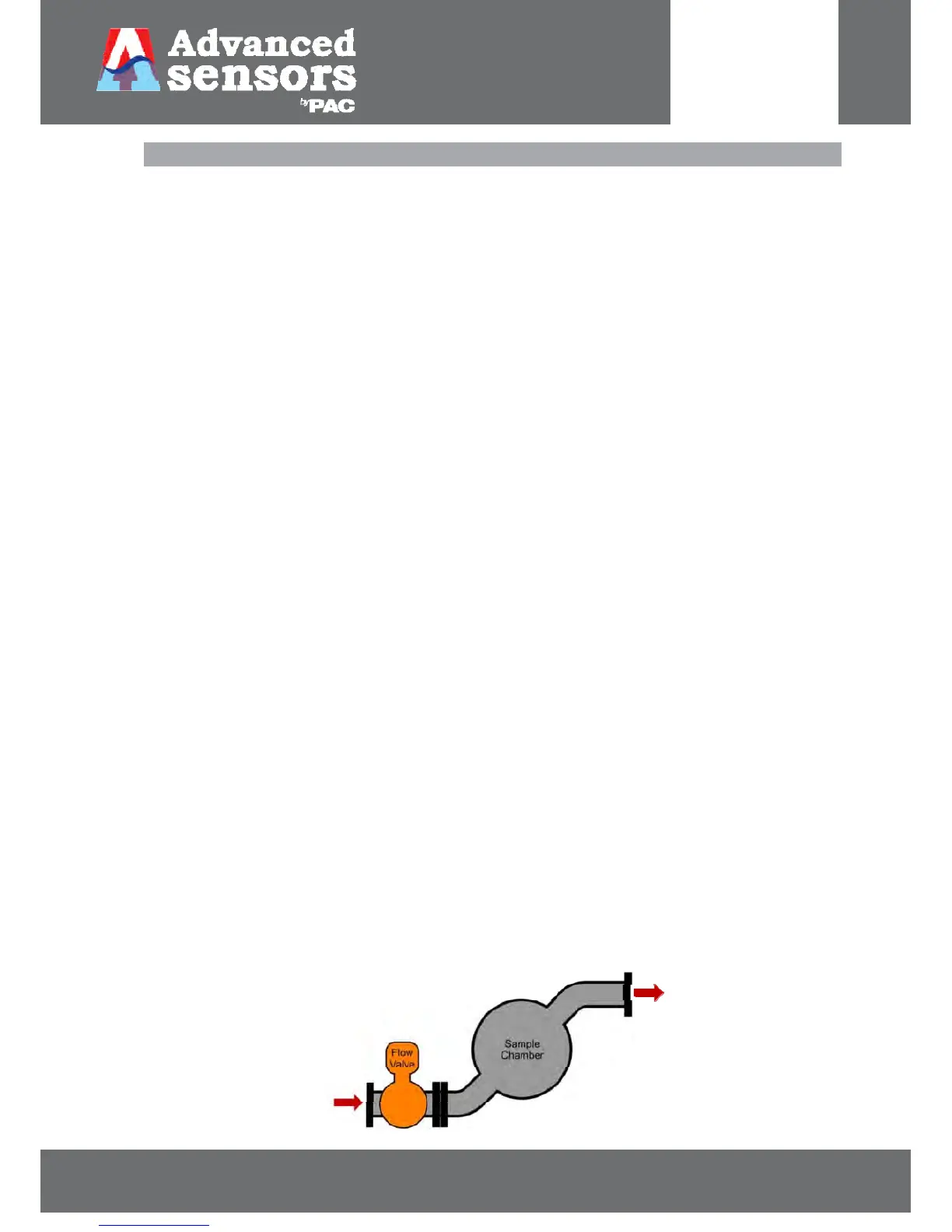
2.3.1.1 – Valve Configurations
Standard configuration requires one valve to control the flow of produced water into the sample chamber as shown
below in Figure 8. Additional information for dual stream systems can be found in Section 6 p.84. Alternative
configurations are also available; please contact your local Advanced Sensors Representative for more information.
Figure 8: Standard Single Valve Configuration
 Loading...