267 ADAM-4000 Series User Manual
Chapter 8 Calibration
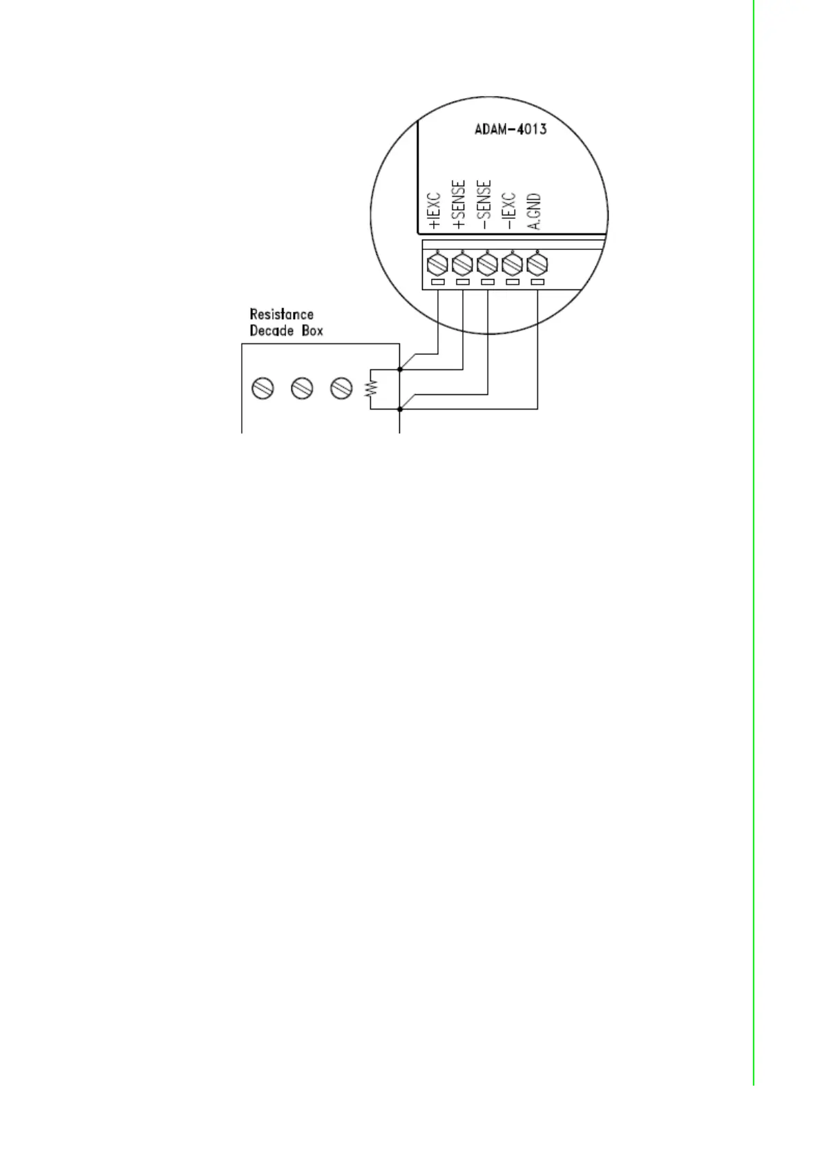
Figure 8.5 Applying calibration resistance
Use a precision resistance decade box or discrete resistors with values:
10 W, 15 W, 60 W, 140 W, 200 W and 440 W.
4. Apply the reference Offset resistance to the terminals of the module. (Please
refer to Figure 8.5 for the correct wiring diagram and Table 8.2 for the right Off-
set calibration resistance.)
5. Issue an Offset Calibration command to the module. This can be done by using
the Calibrate option in the ADAM utility software (Please see Appendix D, Utility
Software)
6. Issue a Span Calibration command to the module. This can be done through the
Calibrate option in the ADAM utility software (Please see Appendix D, Utility
Software)