ADAM-5000 Series User Manual 76
Jumper and Switch Settings
This section tells you how to set the jumpers and switch to configure your ADAM-
5091 module.
There are four jumpers on the PC Board to set RS-232 mode and RS-422/485 mode.
User could select RS-422 master and slave mode via SW1.
Terminal resistors are factory installed to allow for impedance matching. These resis-
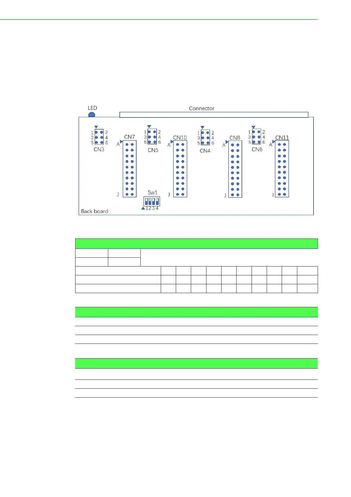
tors can be enabled by utilizing jumper CN3-CN6 for each port (shown below).
Figure 7.7 ADAM-5091 Jumper and switch location
Table 7.6: Jumper Setting
OSHOR T
X OPEN
CN7,CN8,CN10,CN11 A B C D E F G H I J
RS-232 OOOOOXXXXX
RS-422/485(default) XXXXXOOOOO
Table 7.7: Jumper Setting
CN3,CN4,CN5,CN6 120 Ohm 300 Ohm
RS485-DATA/422-TX 1-3 (short) 5-3 (short)
422-RX 2-4 (short) 6-4 (short)
Table 7.8: Switch setting
SW1 COM1 COM2 COM3 COM4
RS-422 MASTER ON ON ON ON
RS-422 SLAVE/RS-485 OFF OFF OFF OFF