SECTION 5
THEORY OF OPERATION
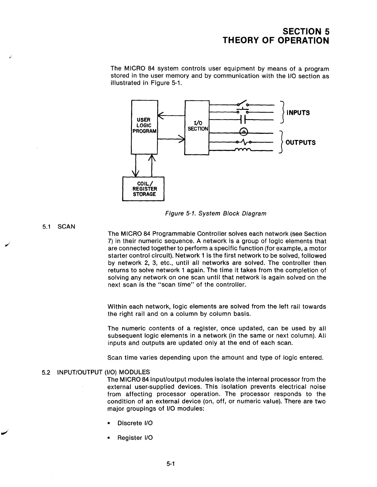
The MICRO 84 system controls user equipment by means of a program
stored in the user memory and by communication with the l/O section as
illustrated in Figure 5-l.
Figure 5-7. System Block Diagram
5.1 SCAN
3
INPUTS
3
OUTPUTS
The MICRO 84 Programmable Controller solves each network (see Section
7) in their numeric sequence. A network is a group of logic elements that
are connected together to perform a specific function (for example, a motor
starter control circuit). Network 1 is the first network to be solved, followed
by network 2, 3, etc., until all networks are solved. The controller then
returns to solve network 1 again. The time it takes from the completion of
solving any network on one scan until that network is again solved on the
next scan is the “scan time” of the controller.
Within each network, logic elements are solved from the left rail towards
the right rail and on a column by column basis.
The numeric contents of a register, once updated, can be used by all
subsequent logic elements in a network (in the same or next column). All
inputs and outputs are updated only at the end of each scan.
Scan time varies depending upon the amount and type of logic entered.
5.2 INPUT/OUTPUT (l/O) MODULES
The MICRO 84 input/output modules isolate the internal processor from the
external user-supplied devices. This isolation prevents electrical noise
from affecting processor operation.
The processor responds to the
condition of an external device (on, off, or numeric value). There are two
major groupings of l/O modules:
l
Discrete l/O
l
Register l/O
5-l
Artisan Technology Group - Quality Instrumentation ... Guaranteed | (888) 88-SOURCE | www.artisantg.com