Benchmark 2.0 LN Installation, Operation & Maintenance Manual
CHAPTER 2 – INSTALLATION
Page 16 of 168 AERCO International, Inc. • 100 Oritani Dr. • Blauvelt, NY 10913 OMM-0046_0J
06/18/2015 Phone: 800-526-0288 GF-123
2.4 SITE PREPARATION.
Ensure that the site selected for installation of the Benchmark 2.0LN Boiler includes:
• Access to AC Input Power at 120 VAC, Single-Phase, 60 Hz @ 20A
• Access to line at a Minimum supply gas pressure of 4" W.C. (2000 cfh for Natural Gas).
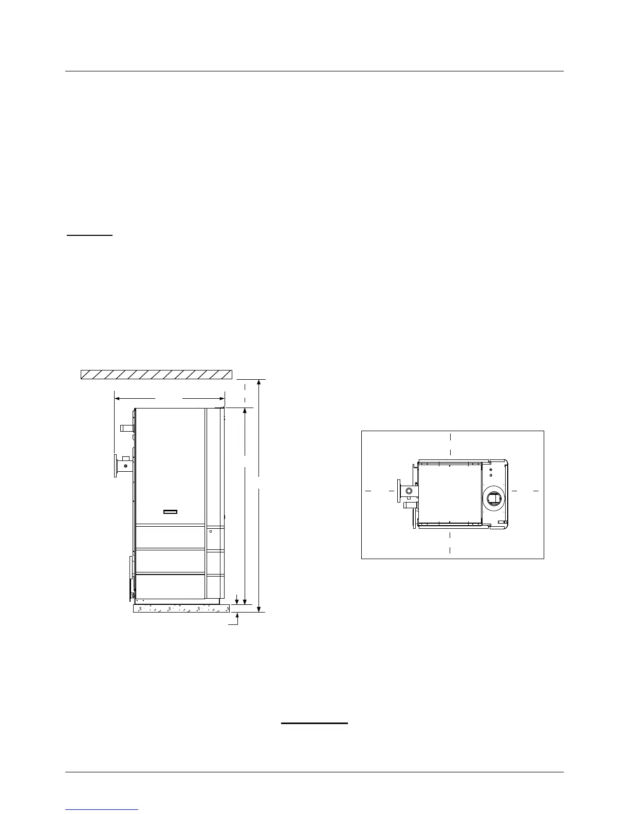
2.4.1 Installation Clearances
The unit must be installed with the prescribed clearances for service as shown in Figure 2-1. The
minimum clearance dimensions, required by AERCO, are listed below. However, if Local Building
Codes require additional clearances, these codes shall supersede AERCO’s requirements.
Minimum acceptable clearances required are:
• Sides: 24 inches
• Front : 24 inches
• Rear: 30 inches
• Top: 18 inches
All gas piping, water piping and electrical conduit or cable must be arranged so that they do not
interfere with the removal of any panels, or inhibit service or maintenance of the unit.
44.5"
18"
79"
101"
4" HIGH PAD*
24"
24"
30"
24"
REAR
FRONT
*(SEE NOTE IN PARAGRAPH 2.4.2)
Figure 2-1: Benchmark 2.0LN Boiler Clearances
WARNING
KEEP THE UNIT AREA CLEAR AND FREE FROM ALL COMBUSTIBLE
MATERIALS AND FLAMMABLE VAPORS OR LIQUIDS.

 Loading...


