Benchmark 2.0 LN Installation, Operation & Maintenance Manual
CHAPTER 2 – INSTALLATION
OMM-0046_0J AERCO International, Inc. • 100 Oritani Dr. • Blauvelt, NY 10913 Page 31 of 168
GF-123 Ph.: 800-526-0288 06/18/2015
Benchmark Venting and Combustion Air Guide, GF-2050. When using the boiler in a sealed
combustion air configuration, each unit must have a minimum 6 inch diameter connection at the
unit.
2.12.4 Ducted Combustion Air
For ducted combustion air installations, the air ductwork is attached directly to the air inlet
connection on the sheet metal enclosure.
In a ducted combustion air application, the combustion air ducting pressure losses must be taken
into account when calculating the total maximum allowable venting run. See the AERCO
Benchmark Venting and Combustion Air Guide, GF-2050. When using the unit in a ducted
combustion air configuration, each unit must have a minimum 8 inch diameter connection at the
unit.
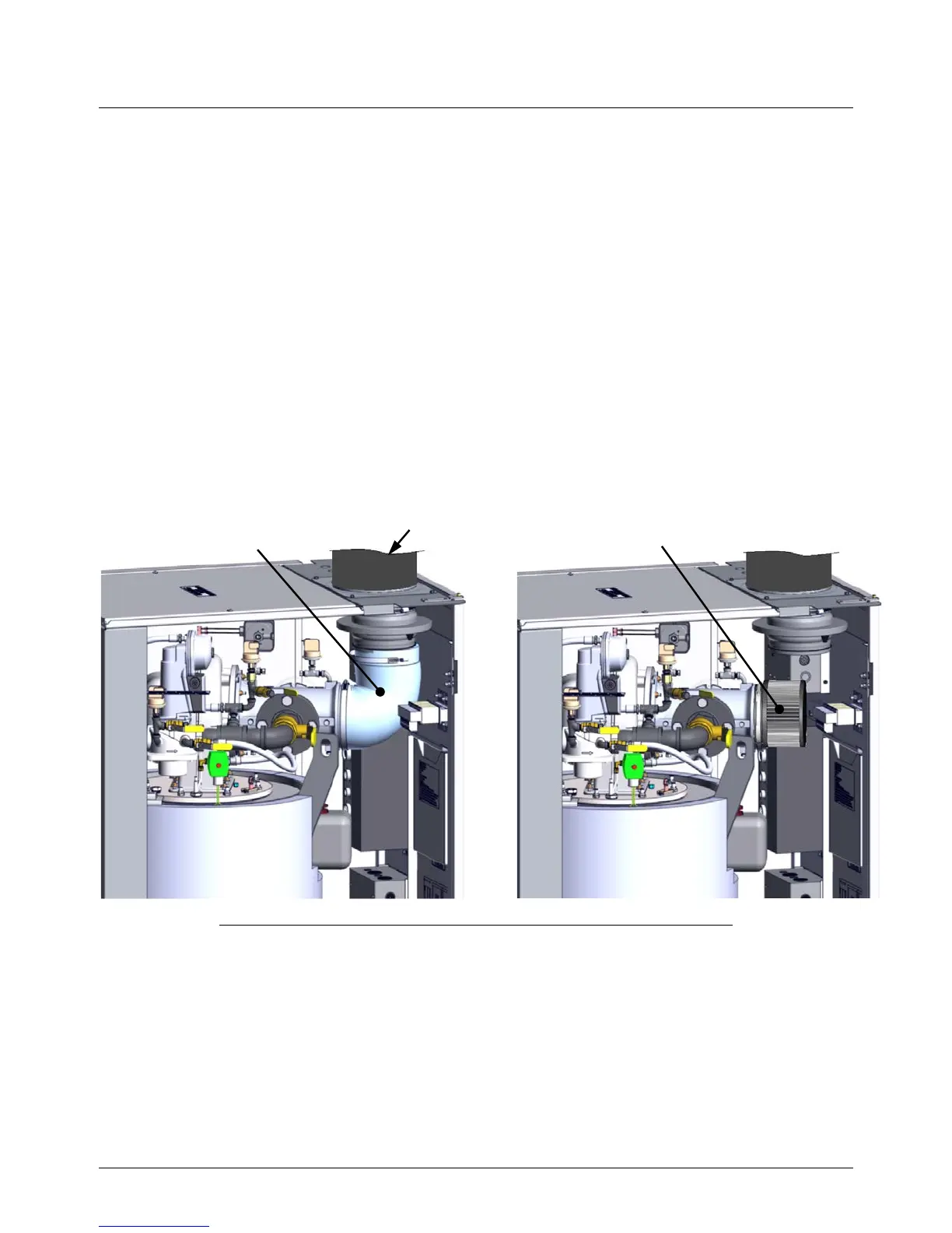
In order to implement this option, you must remove the internal flex hose between the air inlet iris
and the air/fuel valve and install an air filter (AERCO part number 59138) on the air/fuel valve’s
inlet, as shown in the right-hand image in Figure 2-11.
Once the hose has been replaced with the air filter, you must now repeat the combustion
calibration procedure, as described in Chapter 4, section 4.3, below.
PARTIAL LEFT SIDE VIEW – FRONT & LEFT SIDE COVERS REMOVED
Figure 2-11: Location of Ducted Combustion Air Components
2.12.5 Temporary Combustion Air Filtering During Construction
When the Benchmark 2.0LN Boiler is used to provide heat temporarily during ongoing building
construction, accumulated drywall dust, sawdust and similar particles can accumulate in the unit’s
combustion air intake filter and block combustion air flow. In these situations, AERCO recommends
that a disposable air intake filter be installed, temporarily, above the boiler combustion air inlet.

 Loading...


