Benchmark 2.0 LN Installation, Operation & Maintenance Manual
CHAPTER 2 – INSTALLATION
Page 18 of 168 AERCO International, Inc. • 100 Oritani Dr. • Blauvelt, NY 10913 OMM-0046_0J
06/18/2015 Phone: 800-526-0288 GF-123
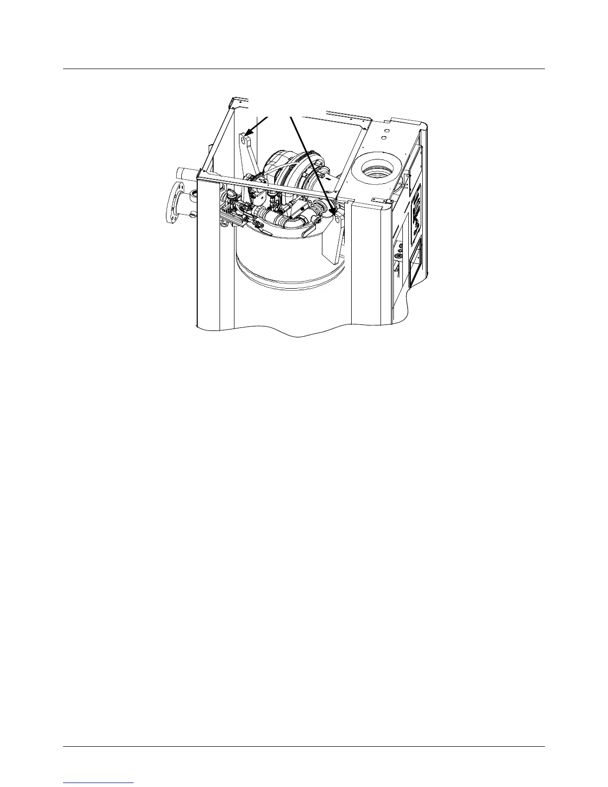
Figure 2-2: Partial Top View Showing Lifting Tab Location
In multiple unit installations, it is important to plan the position of each unit in advance. Sufficient
space for piping connections and future service/maintenance requirements must also be taken into
consideration. All piping must include ample provisions for expansion.
If installing a Combination Control Panel (CCP) system, it is important to identify the Combination
Mode Boilers in advance and place them in the proper physical location. Refer to Chapter 5 for
information on Combination Mode Boilers.
2.5 SUPPLY AND RETURN PIPING
The Benchmark 2.0LN Boiler utilizes 4” 150# flanges for the water system supply and return piping
connections. The physical location of the supply and return piping connections are on the rear of
the unit as shown in Figure 2-3. Refer to Appendix F, Drawing AP-A-798 for additional dimensional
data.

 Loading...


