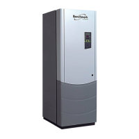
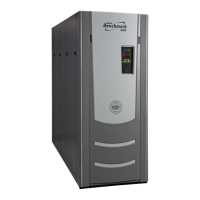
Benchmark 2.0 LN Installation, Operation & Maintenance Manual
OMM-0046_0J AERCO International, Inc. • 100 Oritani Dr. • Blauvelt, NY 10913 Page 3 of 168
GF-123 Ph.: 800-526-0288 06/18/2015
TABLE OF CONTENTS
CHAPTER 1. SAFETY PRECAUTIONS .................................................................................................. 9
1.1 WARNINGS & CAUTIONS .................................................................................................................. 9
1.2 EMERGENCY SHUTDOWN ............................................................................................................. 10
1.3 PROLONGED SHUTDOWN ............................................................................................................. 10
CHAPTER 2. INSTALLATION ............................................................................................................... 15
2.1 introduction ........................................................................................................................................ 15
2.2 RECEIVING THE UNIT ..................................................................................................................... 15
2.3 UNPACKING ..................................................................................................................................... 15
2.4 SITE PREPARATION. ....................................................................................................................... 16
2.4.1 Installation Clearances ............................................................................................................... 16
2.4.2 Setting the Unit ........................................................................................................................... 17
2.5 SUPPLY AND RETURN PIPING ...................................................................................................... 18
2.6 CONDENSATE DRAIN AND PIPING ............................................................................................... 19
2.6.1 Exhaust Manifold Condensate Drain .......................................................................................... 20
2.7 GAS SUPPLY PIPING....................................................................................................................... 21
2.7.1 Gas Supply Specifications. ......................................................................................................... 22
2.7.2 Manual Gas Shutoff Valve .......................................................................................................... 22
2.7.3 External Gas Supply Regulator .................................................................................................. 22
2.7.4 IRI Gas Train Kit ......................................................................................................................... 23
2.8 AC ELECTRICAL POWER WIRING ................................................................................................. 23
2.8.1 Electrical Power Requirements ................................................................................................... 23
2.9 MODES OF OPERATION AND FIELD CONTROL WIRING ............................................................ 24
2.9.1 Constant Setpoint Mode ............................................................................................................. 25
2.9.2 Indoor/Outdoor Reset Mode ....................................................................................................... 25
2.9.3 Boiler Management System Mode.............................................................................................. 25
2.9.4 Remote Setpoint and Direct Drive Modes .................................................................................. 25
2.9.5 Combination Mode ...................................................................................................................... 26
2.10 I/O BOX CONNECTIONS ............................................................................................................... 26
2.10.1 Outdoor Sensor In (1) ............................................................................................................. 27
2.10.2 Air temp. Sensor (2) ................................................................................................................ 27
2.10.3 Analog In (3)............................................................................................................................ 27
2.10.4 B.M.S. (PWM) IN (4) ............................................................................................................... 28
2.10.5 Shield (5) ................................................................................................................................. 28
2.10.6 mA Out (6) ............................................................................................................................... 28
2.10.7 RS-485 COMM (7) .................................................................................................................. 28
2.10.8 TxD, RxD (8) ........................................................................................................................... 28
2.10.9 VFD/Blower (9) ....................................................................................................................... 28
2.10.10 Exhaust Switch In (11) .......................................................................................................... 28
2.10.11 Interlocks (10, 12) ................................................................................................................ 28
2.10.11.1 Remote Interlock In (10) ..............................................................................29
2.10.11.2 Delayed Interlock In (12) ............................................................................29
2.10.12 Fault Relay (13) ..................................................................................................................... 29
2.10.13 Auxiliary Relay Contacts (14) ................................................................................................ 29
2.11 FLUE GAS VENT INSTALLATION ................................................................................................. 29
2.12 COMBUSTION AIR ......................................................................................................................... 30
2.12.1 Combustion Air From Outside the Building .............................................................................. 30
2.12.2 Combustion Air From Inside The Building ................................................................................ 30
2.12.3 Sealed Combustion .................................................................................................................. 30
2.12.4 Ducted Combustion Air ............................................................................................................. 31
2.12.5 Temporary Combustion Air Filtering During Construction ........................................................ 31
2.13 BENCHMARK PUMP RELAY OPTION .......................................................................................... 32
 Loading...
