Benchmark 2.0 LN Installation, Operation & Maintenance Manual
CHAPTER 2 – INSTALLATION
Page 26 of 168 AERCO International, Inc. • 100 Oritani Dr. • Blauvelt, NY 10913 OMM-0046_0J
06/18/2015 Phone: 800-526-0288 GF-123
2.9.5 Combination Mode
NOTE
Only BMS Model 168 and ACS can be utilized for the Combination Mode, not
the BMS II (Model 5R5-384).
With a Combination Mode unit, field wiring is between the unit’s I/O Box wiring terminals, the CCP
(Combination Control Panel), and the BMS (Boiler Management System). For ACS applications,
the wiring is between the ACS panel, the ACS Relay panel (optional, depending on applications),
and the RS-485 Comm terminals in the I/O box. The wiring must be accomplished using twisted-
shielded pair wire from 18 to 22 AWG. Polarity must be maintained. For further instructions and
wiring diagrams, refer to the GF-108 Boiler Management System Operations Guide and the CCP-1
data sheet (BMS 168 applications)/GF-131 and TAG-0050 (ACS applications).
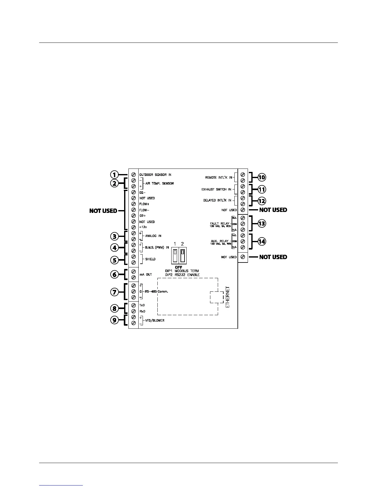
Figure 2-10. I/O Box Terminal Locations and Functions
2.10 I/O BOX CONNECTIONS
The types of input and output signals and devices to be connected to the I/O Box terminals shown
in Figure 2-10 are described in the following paragraphs.
NOTE
Older I/O PCBs are wired the same as new ones, even if silk-screen
designations differ.
NOTE
DO NOT make any connections to the I/O Box terminals labeled “NOT
USED”. Attempting to do so may cause equipment damage.

 Loading...


