Benchmark 2.0 LN Installation, Operation & Maintenance Manual
CHAPTER 3 – OPERATION
OMM-0046_0J AERCO International, Inc. • 100 Oritani Dr. • Blauvelt, NY 10913 Page 45 of 168
GF-123 Ph.: 800-526-0288 06/18/2015
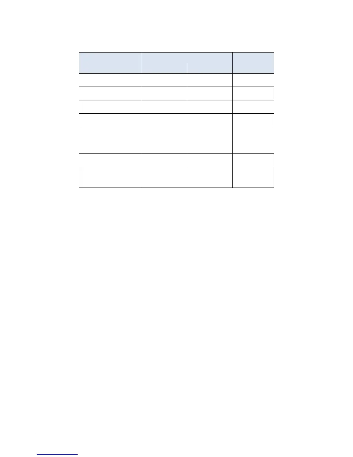
Table 3-6: Combustion Cal Menu
Available Choices or Limits
CAL Voltage 18% .25 10.0v 1.00v
CAL Voltage 30% .25 10.0v 2.30v
CAL Voltage 45% .25 10.0v 2.95v
CAL Voltage 60% .25 10.0v 3.60v
CAL Voltage 80% .25 10.0v 5.30v
CAL Voltage 100% .25 10.0v 9.10v
SET Valve Position 0% 100% 0%
Blower Output Monitor Blower Output
Voltage
.00v
3.9 START SEQUENCE
When the Control Box ON/OFF switch is set to the ON position, it checks all pre-purge safety
switches to ensure they are closed. These switches include:
• Safety Shut-Off Valve Proof of Closure (POC) switch
• Low Water Level switch
• High Water Temperature switch
• High Gas Pressure switch
• Low Gas Pressure switch
• Blower Proof switch
• Blocked Inlet switch
If all of the above switches are closed, the READY light above the ON/OFF switch will light and the
unit will be in the Standby mode.
When there is a demand for heat, the following events will occur:
NOTE
If any of the Pre-Purge safety device switches are open, the appropriate fault
message will be displayed. Also, the appropriate fault messages will be
displayed throughout the start sequence, if the required conditions are not
observed.
1. The DEMAND LED status indicator will light.
2. The unit checks to ensure that the Proof of Closure (POC) switch in the downstream Safety
Shut-Off Valve (SSOV) is closed. See Figure 3-3 for SSOV location.

 Loading...


