Benchmark 2.0 LN Installation, Operation & Maintenance Manual
CHAPTER 3 – OPERATION
Page 46 of 168 AERCO International, Inc. • 100 Oritani Dr. • Blauvelt, NY 10913 OMM-0046_0J
06/18/2015 Phone: 800-526-0288 GF-123
3. With all required safety device switches closed, a purge cycle will be initiated and the
following events will occur:
a) The Blower relay energizes and turns on blower.
b) The Air/Fuel Valve rotates to the full-open purge position and closes purge position
switch. The dial on the Air/Fuel Valve (Figure 3-4) will read 100 to indicate that it is
full-open (100%).
c) The VALVE POSITION bargraph will show 100%.
4. Next, the blower proof switch on the Air/Fuel Valve (Figure 3-5) closes. The display will
show Purging and indicate the elapsed time of the purge cycle in seconds.
5. Upon completion of the purge cycle, the Control Box initiates an ignition cycle and the
following events occur:
a) The Air/Fuel Valve rotates to the low-fire ignition position and closes the ignition
switch. The dial on the Air/Fuel Valve (Figure 3-6) will read between 25 and 35 to
indicate that the valve is in the low-fire position.
b) The igniter relay is activated and provides ignition spark.
c) The gas Safety Shut-Off Valve (SSOV) is energized (opened) allowing gas to flow
into the Air/Fuel Valve.
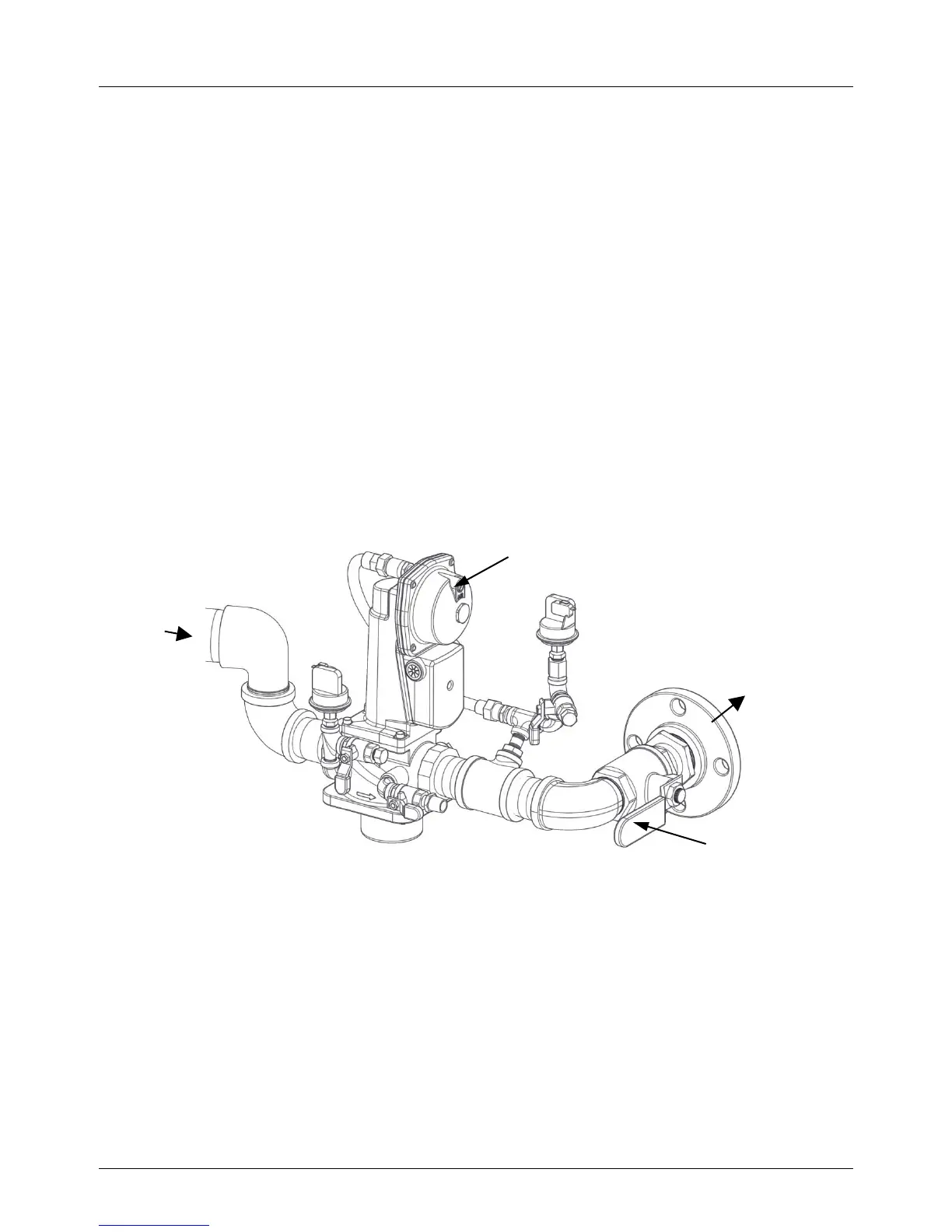
Figure 3-3: SSOV Location
GAS
INLET
VALVE
MANUAL
SHUT-OFF VALVE

 Loading...


