Benchmark 2.0 LN Installation, Operation & Maintenance Manual
CHAPTER 2 – INSTALLATION
OMM-0046_0J AERCO International, Inc. • 100 Oritani Dr. • Blauvelt, NY 10913 Page 19 of 168
GF-123 Ph.: 800-526-0288 06/18/2015
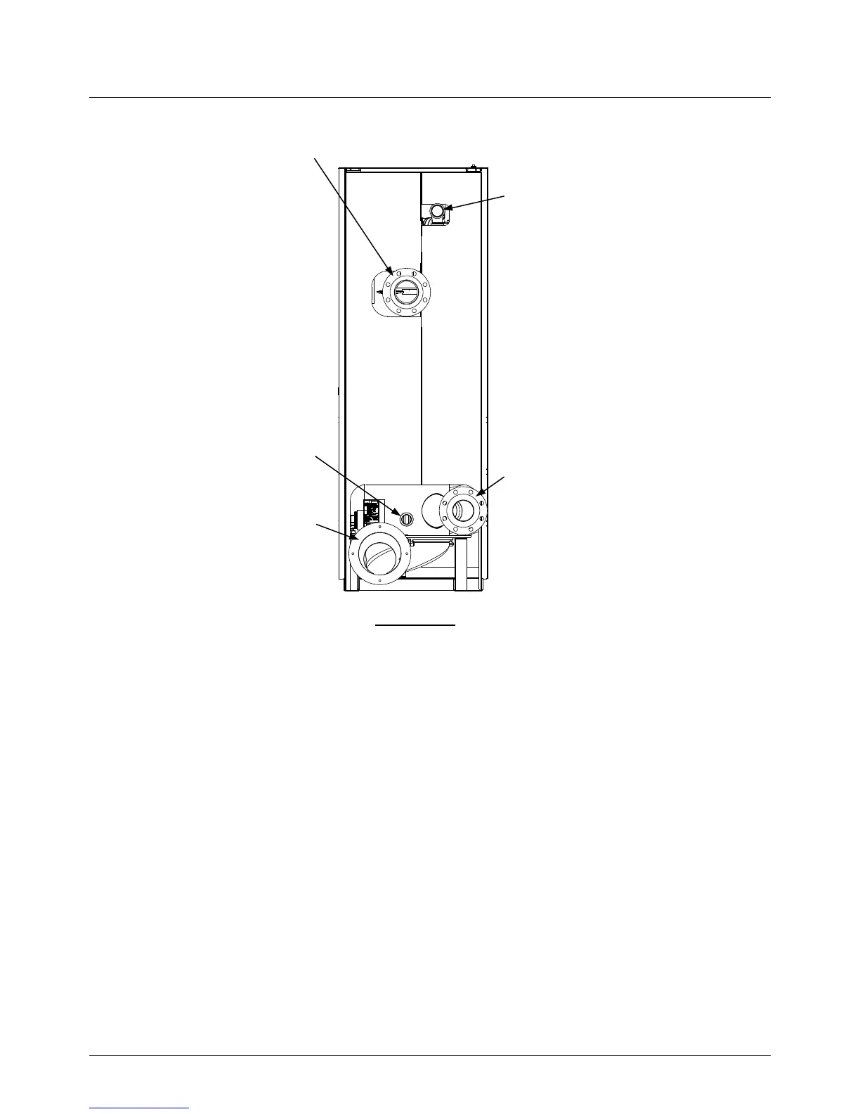
2" GAS INLET
CONNECTION
BOILER RETURN
4" – 150# FLANGE
CONNECTION
BOILER SUPPLY
4" – 150# FLANGE
CONNECTION
EXHAUST
MANIFOLD
SHELL
DRAIN
VALVE
REAR VIEW
Figure 2-3: Supply and Return Locations
2.6 CONDENSATE DRAIN AND PIPING
The Benchmark 2.0LN Boiler is designed to condense water vapor from the flue products.
Therefore, the installation must have provisions for suitable condensate drainage or collection.
The condensate drain pipe located on the exhaust manifold (Figure 2-4) must be connected to a
condensate trap which is packed separately within the unit’s shipping container.
The procedure to install and connect the condensate drain is provided in paragraph 2.6.1.

 Loading...


