Benchmark 2.0 LN Installation, Operation & Maintenance Manual
CHAPTER 3 – OPERATION
OMM-0046_0J AERCO International, Inc. • 100 Oritani Dr. • Blauvelt, NY 10913 Page 43 of 168
GF-123 Ph.: 800-526-0288 06/18/2015
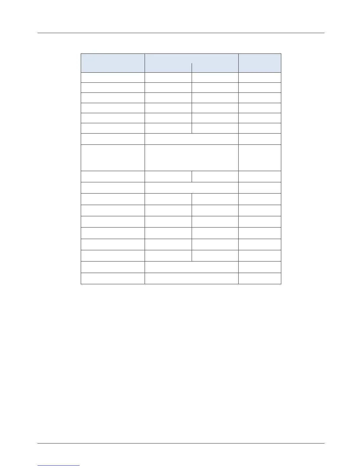
Table 3-4. Configuration Menu - Continued
Available Choices or Limits
Setpt Lo Limit 40°F Setpt Hi Limit 60°F
Setpt Hi Limit Setpt Lo Limit 195°F 195°F
Temp Hi Limit 40°F 210°F 195°F
Max Valve Position 40% 100% 100%
Pump Delay Timer 0 min. 30 min. 0 min.
Aux Start On Dly 0 sec. 120 sec. 0 sec.
Failsafe Mode Shutdown or Constant Setpt Shutdown
*Analog Output
(See CAUTION at
end of Table 3-4 )
Off, Setpoint, Outlet Temp,
Valve Position 4-20 mA,
Valve Position 0-10V
*Valve
Position
0-10V
Low Fire Timer 2 sec. 600 sec. 2 sec.
Setpt Limiting Enabled or Disabled Disabled
Setpt Limit Band 0°F 10°F 5°F
Network Timeout 5 Sec 999 Sec 30 Sec
HI DB Setpt EN 0% 100% 30%
Demand Offsert 0 25 10
Deadband High 0 25 2
Deadband Low 0 25 2
Spark Monitor Enabled or Disabled Disabled
Spark Current Display
NOTE
Only the Unit Sizes applicable to the selected Unit Type will be displayed.
*CAUTION!
DO NOT CHANGE the Analog Output Menu Item from its Default setting
(Valve Position 0-10V).

 Loading...


