Benchmark 2.0 LN Installation, Operation & Maintenance Manual
CHAPTER 4 – INITIAL START-UP
OMM-0046_0J AERCO International, Inc. • 100 Oritani Dr. • Blauvelt, NY 10913 Page 55 of 168
GF-123 Ph.: 800-526-0288 06/18/2015
12. With the valve position at 100%, insert the combustion analyzer probe into the flue probe
opening and allow enough time for the combustion analyzer reading to stabilize.
13. Compare the measured oxygen level to the oxygen range for the inlet air temperature
shown in Table 4-1. Also, ensure that the carbon monoxide (CO) and nitrogen oxide (NOx)
readings do not exceed the values shown.
Table 4-1: Combustion Oxygen Levels for a
100%
Air/Fuel Valve Position
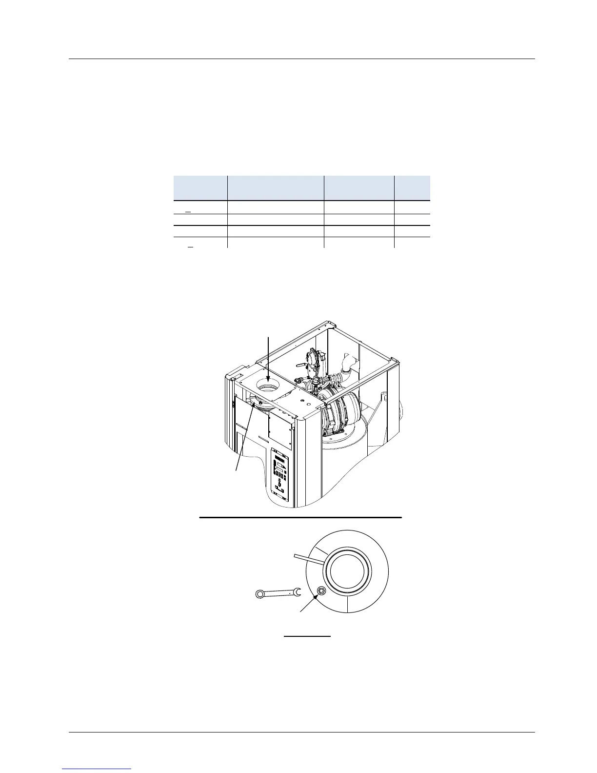
14. If necessary, adjust the iris air damper shown in Figure 4-5 until the oxygen level is within
the range specified in Table 4-1.
15. Once the oxygen level is within the specified range at 100%, lower the valve position to
80%.
AIR
INLET
IRIS AIR
DAMPER
(SEE VIEW
“A”)
USE 1/2"
WRENCH TO
INCREASE
(CW) OR
DECREASE
(CCW) INLET
AIR
IRIS
ADJUSTMENT
VIEW A - A
Figure 4-5: Iris Air Damper Location/Adjustment
NOTE
The remaining combustion calibration steps are performed using
the Combustion Cal Menu included in the C-More Control System.

 Loading...


