software. If you don’t know the NAC of this radio, then we
will try to determine it in step 11.
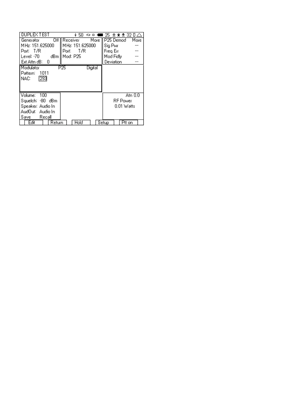
Figure 14 - P25 test setup
8. Connect an RF cable from the T/R port of the 3500A to the
Antenna of the radio.
9. Key up the radio. If you did not know the frequency of the radio
in step 6, then you can move the cursor to the receiver
frequency field, press the “Edit” softkey, and then press the “Find”
softkey.
10. The P25 Demod tile should now be displaying Sig Pwr, Freq Err,
Mod Fidly, and Deviation.
a. Sig Pwr is the power level of the radio, but for direct
connect measurements of power the RF Power meter is a
more accurate measurement. Use the Sig Pwr meter for
over the air measurements, but use the RF Power meter
when you can be directly connected to the radio.
b. Freq Err, Mod Fidly and Deviation are measurements of
the modulation fidelity. For more information on
understanding these measurements, see the section on
Understanding the modulation fidelity parameters.
11. Move the cursor to the “More” field in the P25 Demod tile and
press the “Enter” softkey until you can view the NAC decode
field. This value should match the expected value for the NAC
from the radio under test. You can also use this value for the
NAC value in the Modulator tile, if you didn’t know what the NAC
of this radio was.
12. Press the “Ptt on” softkey.
13 .You should now hear the test tone in the radio. If you don’t hear
a tone, check the following.
a. Make sure that the Generator is on by observing the
indication in the upper right hand corner of the Generator
tile.
b. Check that the Generator frequency is set to the receive
frequency of the radio and that the RF Level is greater than
the sensitivity of the radio.
c. The NAC field in the Modulator tile must match the NAC
of the radio. If you are unsure of the NAC then go back to
step 11.
14. If you have the capability and are able to use test software to
put the radio into test mode, you can also measure the BER of
the receiver and verify the sensitivity of the radio.
a. Put the radio into the test mode.
b. Select the 1011 pattern in the modulator tile of the 3500A.
c. Set the NAC to 293.
d. Select the 1011 pattern in the radio test software.
e. The radio test software should now be able to display the
bit error rate. Lower the level of the generator in the
3500A until the BER is ~5%. This is the sensitivity of the
receiver of the radio.
After you have setup the 3500A for this test, you can save the setup
so that you do not need to go through these steps again. See the
section on Saving and Recalling setups for quick testing.
3.2 NXDN™ Radio Test
In this test we will show how to make the key measurements
necessary to verify the proper operation of an NXDN mobile,
including the modulation fidelity parameters of the transmitter and
BER of the receiver. We will do this from the DUPLEX TEST screen.
1. Enter DUPLEX TEST screen.
2. Select the “Setup” softkey.
3. Place a 3 next to Digital Receive and a 9 next to RF Power Meter.
The other selections should have a 0 next to them.
4. Press the “Return” softkey.
5. In the Generator tile
a. Set the frequency to be the same as the receive
frequency of the radio.
b. Set the Port to T/R.
c. Set RF level to a nominal level (-70 dBm is good).
d. Set the Ext Atten field to the loss of the cable or if an
attenuator is being used, the value of the attenuator.
e. Set the Generator to off by pressing the far right softkey
until the indication in the upper right hand corner of the
generator tile is “Off”.
6. In the Receiver tile
a. Set the frequency to be the same as the transmit
frequency of the radio. If you do not know the transmit
frequency, we will find it in step 8.
b. Set the Port to T/R.
c. Set the Mod to NXDN.
d. If an attenuator is being used, move the cursor to the
“More” field and press the “Enter” softkey. You can now
enter the value of the attenuator into the atten field.
7. In the Modulator tile
a. In the upper right hand corner, select Digital.
b. Press the up arrow key and then select NXDN from the list
of modulation types.
10