For the very latest specifications visit www.aeroflex.com
3
1 Basic Operating Principles of the 3500A
In this first section, I am going to outline some of the general
operating concepts of the 3500A. Knowing these operational
concepts will enable you to get the most out of your 3500A. Read
this section first and then apply these concepts when following any
of the instructions in the other sections of this application note.
When you first power on your 3500A, you will notice that it takes less
than forty seconds to boot up to the System screen. Here you will
find a menu enabling access to all of the standard and optional test
screens of the 3500A. From this location you can quickly move to
any of the 3500A radio test functions or instrument screens. At the
bottom, you will also see four softkeys that allow you to access other
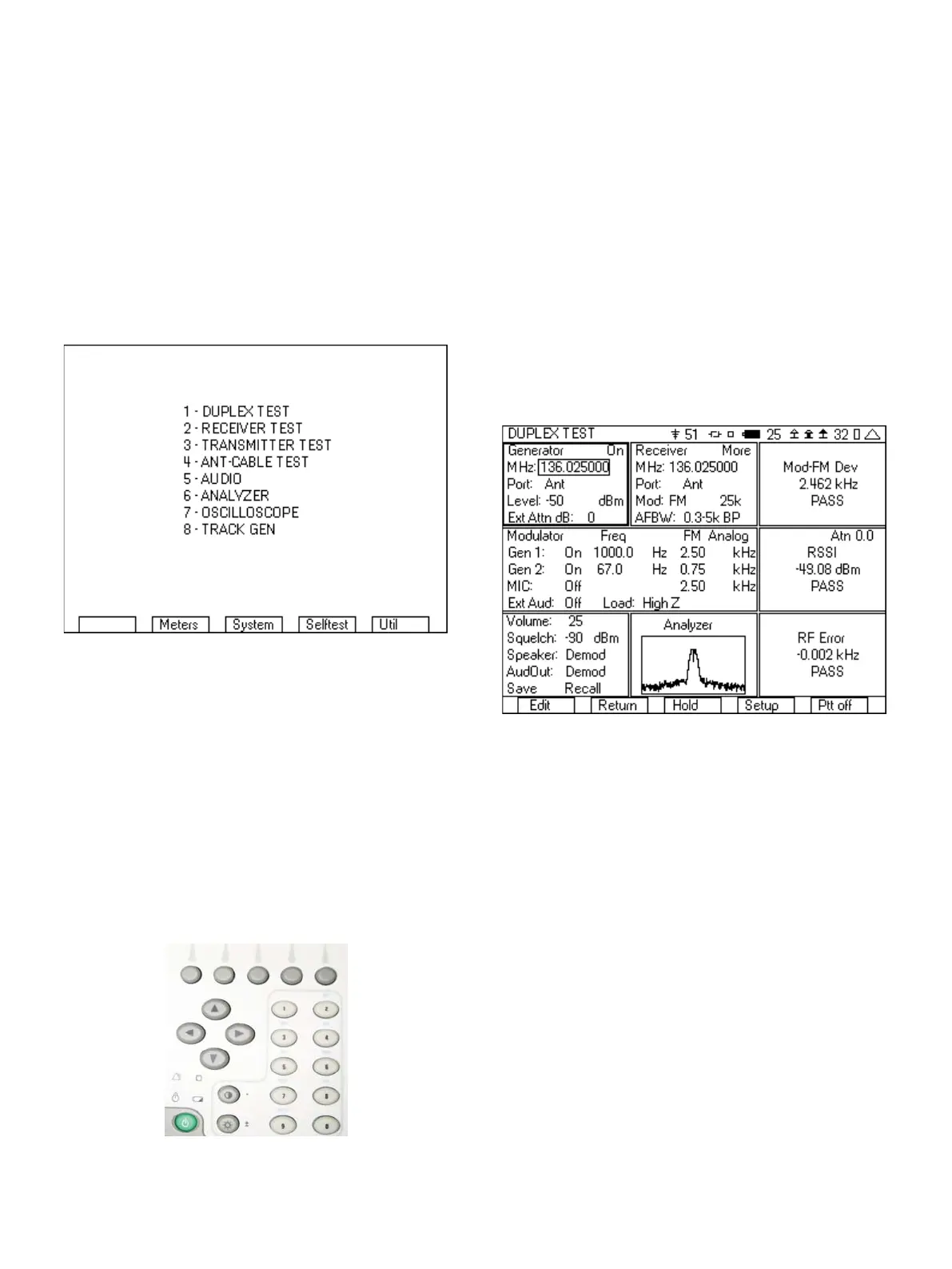
menus. Figure 1 shows the System screen when all of the options are
installed in the 3500A.
Figure 1 - System screen
The test screens that can be accessed from this menu could be
divided into two categories. These two categories will be called the
radio test screens and the instrument screens. The selections from
this menu allowing access to radio test screens are 1, 2, 3 and 5 and
the instrument screens are 4, 6, 7 and 8. The next two sections will
outline some of the key operating principals for these screens.
1.1Radio Test Screens
Selections 1, 2, 3 and 5 in the System menu are the radio test
screens and are very similar in operation. Each of these screens is
created with up to nine tiles (see Figure 3). Navigating through the
fields in these nine tiles is primarily accomplished using the four
arrow keys.
Figure 2 - Front panel of the 3500A
The up and down arrow keys are used to control movement of the
cursor, with the down arrow moving the arrow in a forward direction
and the up arrow moving the cursor in a reverse direction. Even if
moving the cursor to the right, the down arrow must be use.
Conversely, when moving the cursor to the left, the up arrow must be
used.
The right and left keys are used for moving the cursor from tile to tile.
Think of these keys as your +/- tab keys. The right key moves through
the tiles in the forward direction. If you are in the lower right hand tile,
pressing the right arrow will move to the upper left tile. Conversely
the left arrow moves the opposite direction. You can move quickly to
any tile on the screen in no more than four key presses.
Figure 3 shows the DUPLEX test screen and the five softkeys. The
first softkey is context sensitive and will change based on the
location of the cursor. If the cursor is on an editable field, then this
softkey is labeled “Edit”. If the cursor is located on a meter or
instrument label then this softkey is labeled “Zoom”. If the cursor is
on a “More” field, then this softkey is labeled “Enter”.
Figure 3 - Duplex test screen showing tile layout and softkeys
If located on an editable field, you will find that there are different
ways of editing the parameters of this field. If it is a numeric field, you
can simply start entering the numeric value and the editing state will
immediately be activated. If it is a “list” field, that has three or more
selections, then pressing the “Edit” key will change the field into an
edit mode, with the up/down arrows used to select the desired entry
from a list. If the list only includes two items then pressing the “Edit”
softkey will toggle the field to the other entry. After entering the “Edit
mode”, the labels on the softkeys change, so that the first softkey is
labeled “Done” and the fifth softkey is labeled “Esc”. Press the “Done”
softkey after the desired value is selected, or “Esc” if you have
entered a value, but do not want to use it.
When the first softkey label is “Zoom”, pressing this key will
maximize the selected tile, with more user selectable fields and
information presented. When the maximized tile is a meter, the
“Zoomed” in tile includes setup fields for pass/fail criteria, as well as
a bar graph of the meter. When the maximized tile is an instrument,
either scope or analyzer, the “Zoomed” in meter has a larger
instrument display as well as the setup fields for controlling the
instrument.