5. In the Modulator tile:
a. In the upper right hand corner of this tile select DCS (other
selections are Analog, Digital and DTMF).
b. Set the Modulation to FM.
c. Setup Gen1 to On 1000.0 Hz 3.00 kHz.
d. Setup DCS to Non Inv with 0.30 kHz of deviation. Enter the
three digit DCS code of your radio. If you don’t know the
DCS code then we will decode it in step 9.
e. MIC and Ext Aud should be off.
6. In the Mod-FM Dev tile:
a. Press the “Zoom” softkey.
b. Move cursor down to the Avg Reading field and set it to
10.
c. Press the “Return” softkey.
7. In the lower left hand tile:
a. Set the volume to 100.
b. Set the squelch level to -80 dBm.
c. Select Demod for the Speaker.
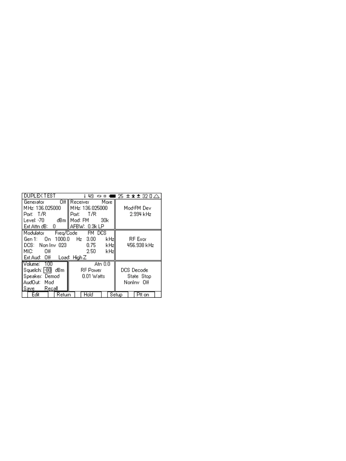
Figure 10 - FM with DCS test setup
8. Move your cursor over to the DCS decode tile.
9. Key up your radio and then press the “Enter” softkey. The DCS
decode tile will display the DCS code. If you did not know the
DCS value in step 5, then you can use this in the modulator tile.
If you are not decoding a DCS value, then check the following.
a. Verify with the RF power meter that the radio is
transmitting.
b. Check the RF Error meter. If it is measuring a large amount
of frequency error, then the radio may be transmitting on
a different frequency, or the timebase may be out of spec.
c. The other possibility is a problem with the modulator of the
radio, or maybe it is on a channel that does not use DCS.
10. After decoding the DCS, press the Enter softkey to change the
Decode state to Stop.
11. Continue to key up the radio and measure the FM deviation of
the DCS, the RF Power, and the RF (frequency) Error.
12. Unkey the radio and select the “Ptt On” softkey. The Generator
On/Off indication in the Generator tile should change to say On.
You should now near the 1000 Hz tone in the radio. If you do
not hear a tone, then check the following.
a. Make sure that the DCS code in the modulator tile is
correct value for the receiver.
b. Check that the Generator is On and that the RF level is
above the receive sensitivity of the radio.
c. Verify that the 3500A generate frequency matches the
receive frequency of the radio.
After you have setup the 3500A for this test, you can save the setup
so that you do not need to go through these steps again. See the
section on Saving and Recalling setups for quick testing.
2.2 FM Duplex Radio with Tone Squelch Testing
You can also test a radio that uses a tone to open up the squelch
of the receiver of the radio. With the 3500A you will be able to both
generate a squelch tone and measure the frequency and deviation
of the tone transmitted by the radio.
For this test, the T/R port of the 3500A should be interfaced to the
antenna of the radio. An attenuator will be needed if the transmit
power of the radio is greater than 20 watts.
Here are step by step instructions on how you can test this type of
channel.
1. Select the DUPLEX TEST screen.
2. Press the “Setup” softkey.
a. Place a 3 next to Modulation Meter.
b. Place a 6 next to RF Error Meter.
c. Place an 8 next to RF Power Meter.
d. Place a 9 next to AF Counter.
e. Press the “Return” softkey.
3. In the Generator tile:
a. Enter the receive frequency of the radio.
b. Select the T/R port.
c. Enter RF Level (set to a nominal level, example uses -70).
d. Enter the cable loss or if using attenuator, the attenuator
loss.
e. Set the Generator to Off by pressing the far right softkey
(this key toggles the generator on and off).
4. In the Receiver tile:
a. Enter the transmit frequency of the radio.
b. Select the T/R port.
c. Select FM for Mod:
d. The value to the right of Mod is the selection for the
bandwidth of the signal. Make sure that this is greater than
the bandwidth of the signal from the radio. If this selection
is too narrow, the modulation measurement will be wrong.
For this example it will be set to 30k.
6