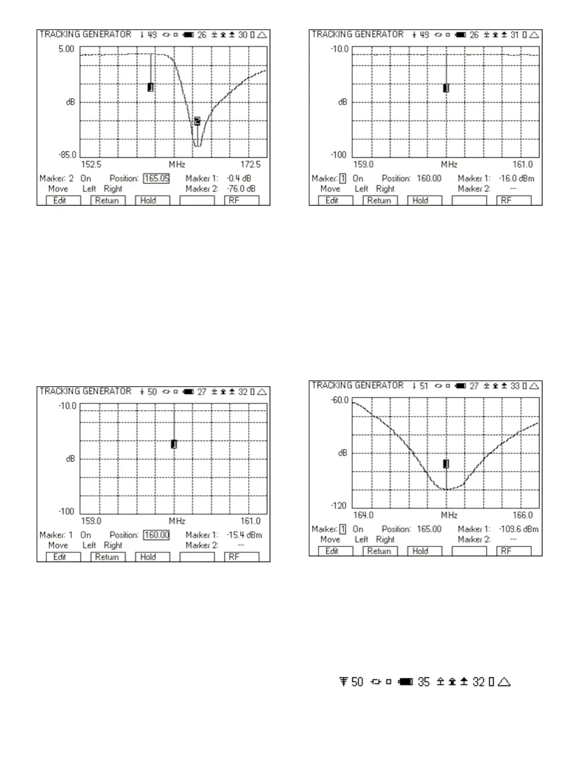
Figure 32 - Tracking Generator with markers
8.2.1 Measuring the Pass Band
1. Set the “Freq (MHz)” and “Span (MHz)” fields to focus on the pass
band.
2. Set the “Ref Lvl” field to -10.
3. Turn the Preamp to On.
4. Change the Markers so that one is right on the center
frequency.
5. Connect the cables together through a barrel connect.
6. Read the Marker level.
Figure 33 - Pass band ref level
7. Insert the duplexer.
8. Read the Marker level.
9. The pass band loss is the difference between Figure 33 and
Figure 34.
Figure 34 - Pass band loss
8.2.2 Measuring the Reject Band
1. Set the “Freq (MHz)” and “Span (MHz)” fields to zoom in on the
reject band.
2. Set the “Ref Lvl” field to -60.
3. Set the “Scale” to 10.
4. Change the Markers so that one is right on the center
frequency.
5. The rejection then is the difference between Figure 33 and
Figure 35.
Figure 35 - Zooming in to the reject band of the duplexer
9 Other Keys to Getting the Most Out of Your 3500A
9.1 Top of Screen Icons
There are several icons at the top of the screen in the radio test and
instrument screens. These icons indicate information to the user of
the status of various items.
Figure 36 - 3500A icons
These are the icons you should give special attention.
18