For the very latest specifications visit www.aeroflex.com
modulation called 4FSK, which stands for 4-level Frequency Shift
Keying modulation. In this modulation, the digital data is conveyed
by shifting the frequency of the RF carrier to four distinct levels.
These digital radio systems and their four frequency shifts (Hz) are
shown in the following table.
Table 1 - Frequency shifts (Hz)
These frequency shifts of the carrier are done smoothly, through
standard specific filters, which prevent abrupt changes in the
carrier frequency that would result in the bandwidth of the signal
being excessive, but still allow the frequency shifts to accurately
occur.
The 3500A is able to both transmit using this modulation to test
these digital receivers as well as make key modulation
measurements on signals from the radios conforming to these
standards. These key measurements on the modulation along with
the generate modulation provide the user with an important
determination of the proper operation of the digital operation of the
base station or mobile station under test.
These key measurements of modulation fidelity for DMR, NXDN
and P25 are FSK error, Symbol deviation and frequency error. In
P25, the FSK error measurement is known simply as modulation
fidelity. Also important for DMR mobile stations is a measurement of
the amount of magnitude error. It is important that a DMR mobile
transmit a burst that has a constant power level across the slot time,
so that the information contained in the burst can be accurately
decoded. For more information on these important modulation
parameters, see the section on Understanding the Modulation
Fidelity Parameters.
The 3500A can also generate using 4FSK modulation, using
patterns defined by the various radio standards. These standard
patterns include a test tone pattern, a random data pattern and
a pattern with a predefined number of bit errors called the Cal
pattern. The test tone pattern called 1011 or 1031 is useful for
performing a simple audio check on the receiver. The random data
pattern is often used to check the bit error rate of the radio. This is
done with the radio in a test mode with the radio measuring and
reporting the BER. The Cal pattern is used to check the ability of the
radio to count bit errors accurately since it contains a predefined
number of errors.
The standards used for these radio tests:
P25 – TIA.102-CAAA
DMR Radio Standard - ETSI TS 102 361-1
NXDN™ Radio Standard – This standard is a document from the
NXDN™ Forum
3.1 P25 Radio Test
In this test, we will show how to make the key measurements
necessary to verify the proper operation of a P25 mobile,
including the modulation fidelity parameters of the transmitter and
BER of the receiver. We will do this from the DUPLEX TEST screen.
1. Enter DUPLEX TEST screen.
2. Select the “Setup” softkey.
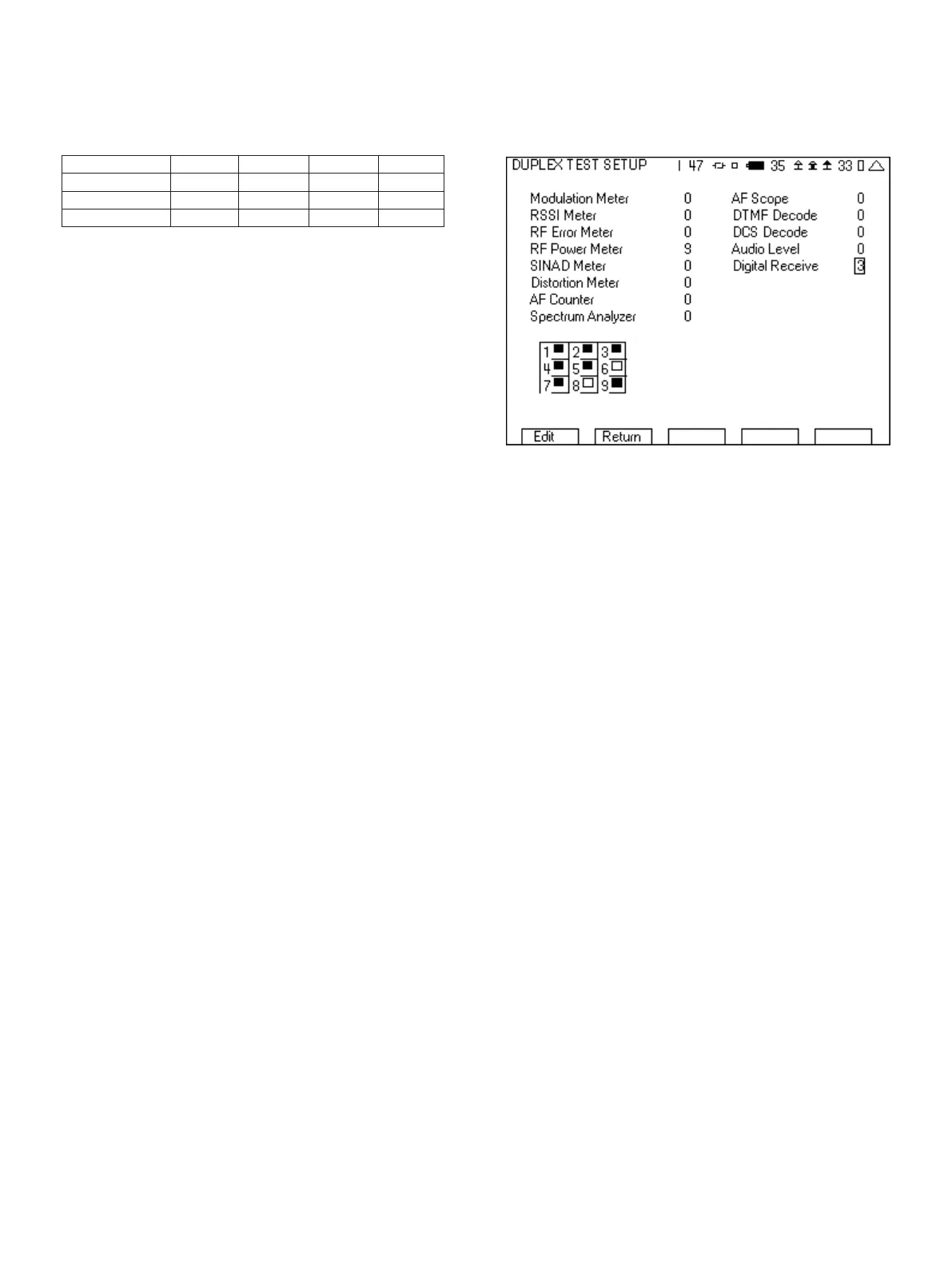
3. Place a 3 next to Digital Receive and a 9 next to RF Power Meter.
The other selections should have a 0 next to them.
Figure 13 - Duplex test setup screen for P25
4. Press the “Return” softkey.
5. In the Generator tile
a. Set the frequency to be the same as the receive
frequency of the radio.
b. Set the Port to T/R.
c. Set RF level to a nominal level (-70 dBm is good).
d. Set the Ext Atten field to the loss of the cable or if an
attenuator is being used the value of the attenuator.
e. Set the Generator off by pressing the far right softkey until
the indication in the upper right hand corner of the
generator tile is “Off”.
6. In the Receiver tile
a. Set the frequency to be the same as the transmit
frequency of the radio. If you do not know the transmit
frequency, we will find it in step 8.
b. Set the Port to T/R.
c. Set the Mod to P25.
d. If an attenuator is being used, move the cursor to the More
field and press the Enter softkey. You can now enter the
value of the attenuator into the atten field.
7. In the Modulator tile
a. In the upper right hand corner, select Digital.
b. Press the up arrow key and then select P25 from the list
of digital modulations.
c. For the pattern, select 1011.
d. The NAC must be the same as the NAC (Network Access
Code) in the radio that you are testing. The NAC is
programmed into the radio using the programming
NXDN - 4800 -1050 -350 350 1050
NXDN – 9600 -2400 -800 800 2400
DMR -1944 -648 648 1944
P25 -1800 -600 600 1800
9