For the very latest specifications visit www.aeroflex.com
7. Using the far right softkey, switch to the Marker page.
8. Turn on Marker 1.
9. The position of the marker can be selected from the Pos field, or
by moving the cursor to the Min/Max/Move field. From this field
you can move the cursor to the Minimum VSWR, the
maximum VSWR, or just move the cursor to the right or left, using
the Right and Left field.
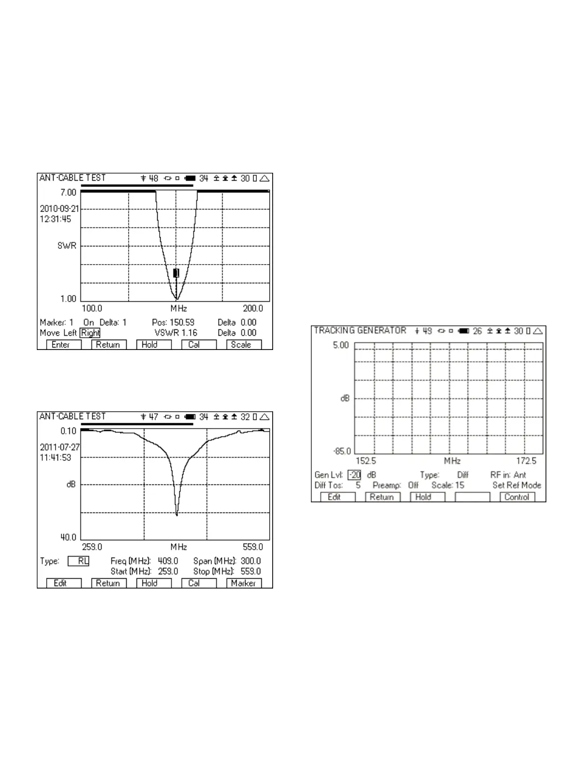
10. Figure 29 shows a sweep of a VHF antenna. The marker is
shown after moving it to the minimum VSWR. The VSWR field
displays the VSWR at the frequency given by the Pos field.
Figure 29 - VSWR with marker
11. If RL was selected, the operation is the same, but the display will
be shown in dB return loss.
Figure 30 - Return Loss Sweep
8 Tuning a Duplexer
The 3500A tracking generator option can be used to check the
operation or tune duplexers and filters. It could also be used with a
return loss bridge to look at the return loss of an antenna or
duplexer. The signal sweep is generated from the SWR port, with
the receive signal measured at either the T/R port or the Ant port.
The following is step by step instructions for tuning a duplexer. The
duplexer used in this example has a passband of 160 MHz and
reject band of 165 MHz. The following are the step by step
instructions that you can follow for tuning this duplexer.
8.1 Setting the Reference Mode for Maximum Dynamic
Range
1. Remove cables from the 3500A Ant and SWR ports.
2. Set the “Freq (MHz)” and “Span (MHz)” fields as needed for the
duplexer being tuned.
3. Set the “Gen Lvl” field to -20 dB.
4. Set the “RF in” field to Ant.
5. Set the “Ref Lvl” field to -30.
6. Set “Preamp” to Off.
7. Set “Scale” to 15.
8. Connect test cables to the SWR port and to the ANT port.
9. Connect the test cables together (for example using a barrel
connector).
10. Move cursor to “Set Ref Mode” and press the “Enter” softkey.
11. Move cursor to “Diff Tos” and set to 5.
12. The screen should now look like Figure 31.
Figure 31 - Tracking Generator screen
8.2 Measuring the Duplexer
1. Insert the duplexer in place of the barrel connecting the two
cables.
2. Using the right softkey, go to the markers screen and turn on the
markers.
3. Set the frequency of the markers to the frequencies of interest.
4. From this setup, make the adjustments to the UUT pass band and
reject band. After tuning, the display should look something like
Figure 32.
17