For the very latest specifications visit www.aeroflex.com
Figure 8 - Analyzer screen
As can be seen in Figure 8, the right softkey is labeled “Marker”.
When this key is pressed, the setup area beneath the display will
change to the marker fields. The last softkey will also change and
will indicate the next set of setup fields. In fact, this softkey label will
always indicate what the next set of setup fields beneath the display
will be if pressed. Pressing this repeatedly will rotate through the
various setup fields available. This operation of using the right most
softkey to control the setup fields is true for all of the instrument
screens.
2 FM Radio Transceiver Testing with the 3500A
The 3500A is ideal for both quick and thorough testing of FM
transmitters and receivers. With the 3500A, you can tests FM radios
with a level squelch, tone squelch or digital squelch. The tone
squelch is often referred to as PL tone or more generically as
CTCSS. Digital squelch is also know as DPL and DCS, but is
generically called CDCSS (The 3500A calls it DCS).
CTCSS – continuous tone coded squelch system
CDCSS – continuous digital coded squelch system
PL – Private Line
DPL – Digital Private Line
DCS – Digitally Coded Squelch
Private Line and Digital Private Line are trademarked by Motorola.
In addition to digital and tone squelch testing, the 3500A is
capable of testing DTMF by both encoding and decoding DTMF.
The following sections include the step by step instructions for FM
radio transceiver testing.
2.1 FM with DCS Radio Test
The purpose of this test will be to generate a 1000 Hz tone to the
radio while opening up the squelch with the correct DCS squelch
code. You will also decode the squelch code of the radio, while
measuring the RF power and frequency error.
For this test, the T/R port of the 3500A should be interfaced to the
antenna of the radio. An attenuator will be needed if the transmit
power of the radio is greater than 20 watts.
Here are the step by step instructions.
1. Select the DUPLEX TEST screen.
2. Press the “Setup” softkey.
a. Place a 3 next to Modulation Meter.
b. Place a 6 next to RF Error Meter.
c. Place an 8 next to RF Power Meter.
d. Place a 9 next to DCS Decode.
e. Press the “Return” softkey.
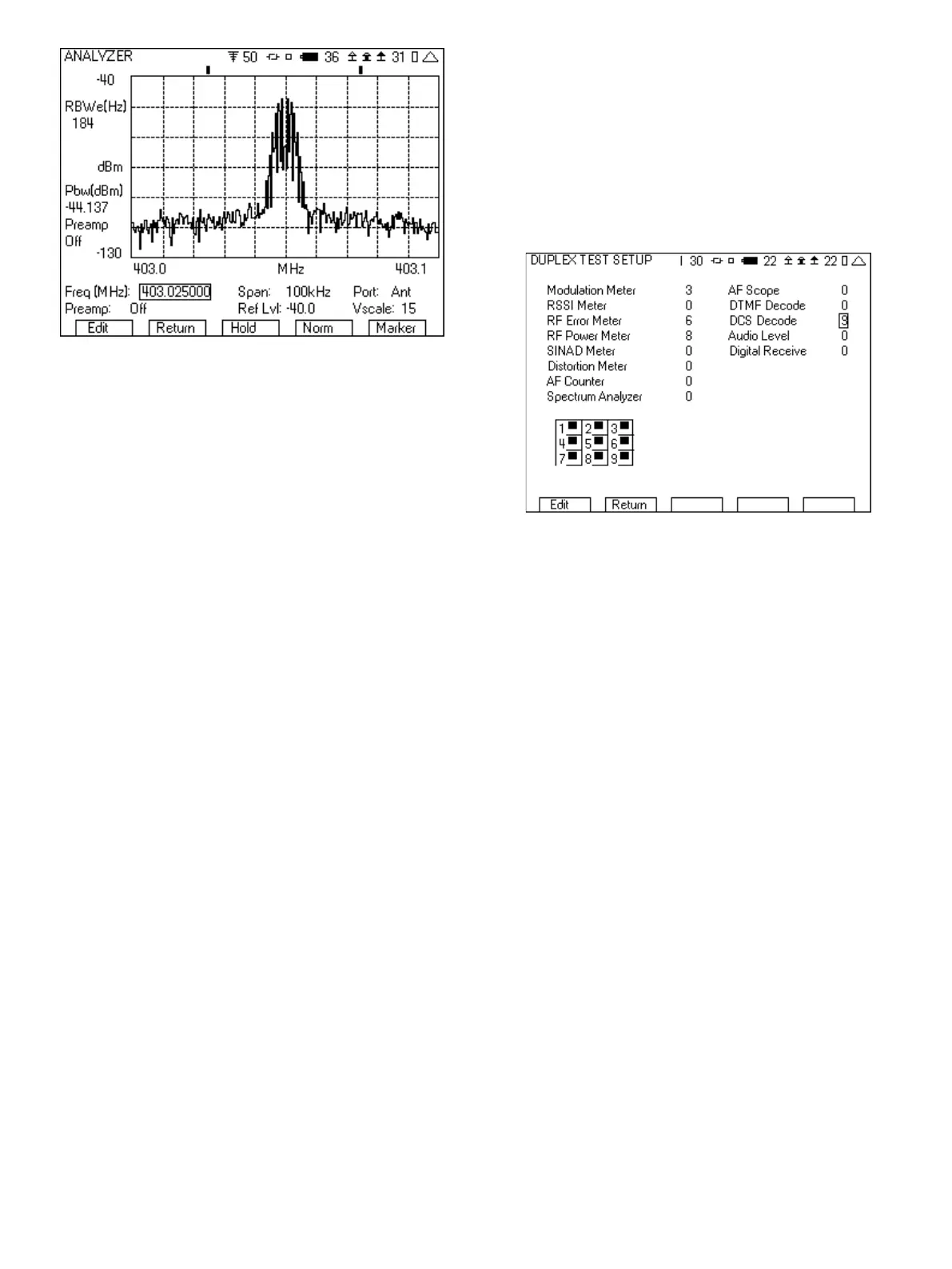
Figure 9 - DUPLEX TEST SETUP screen for DCS
3. In the Generator tile:
a. Enter the receive frequency of the radio.
b. Select the T/R port.
c. Enter RF Level (set to a nominal level, example uses -70).
d. Enter the cable loss or if using attenuator, the attenuator
loss.
e. Set the Generator to Off by pressing the far right softkey
(this key toggles the generator on and off).
4. In the Receiver tile:
a. Enter the transmit frequency of the radio.
b. Select the T/R port.
c. Select FM for Mod:
d. The value to the right of Mod is the selection for the band-
width of the signal. Make sure that this is greater than the
bandwidth of the signal from the radio. If this selection is
too narrow, the modulation measurement will be wrong.
For this example, it will be set to 30k.
e. AFBW (Audio Frequency Bandwidth) should be set as
needed for the type of test. We want to measure the DCS,
so set this to 0.3k LP (300 Hz lowpass). This will
filter out the audio while letting through the DCS signal.
f. If using an attenuator, the attenuation value can be
entered in the Ext Attn dB field, located after selecting
“More”.
5