This measurement requires a calibration to be performed using a
short, open and load, included with the test set. Calibration for this
measurement does not need to be done before each
measurement. The following guidelines could be followed to
determine when a new calibration is necessary.
1) If the cable that you are using to connect from the 3500A to the
cable you are testing has changed then you must do
another calibration. Make sure you do this calibration at the end
of this cable and not right on the SWR connector. This will
calibrate out the length of this cable.
2) If the environmental conditions have changed since the last
calibration, then do another calibration.
3) A date on the screen indicates the last time a calibration was
performed. If this is more than a day old, then do another
calibration.
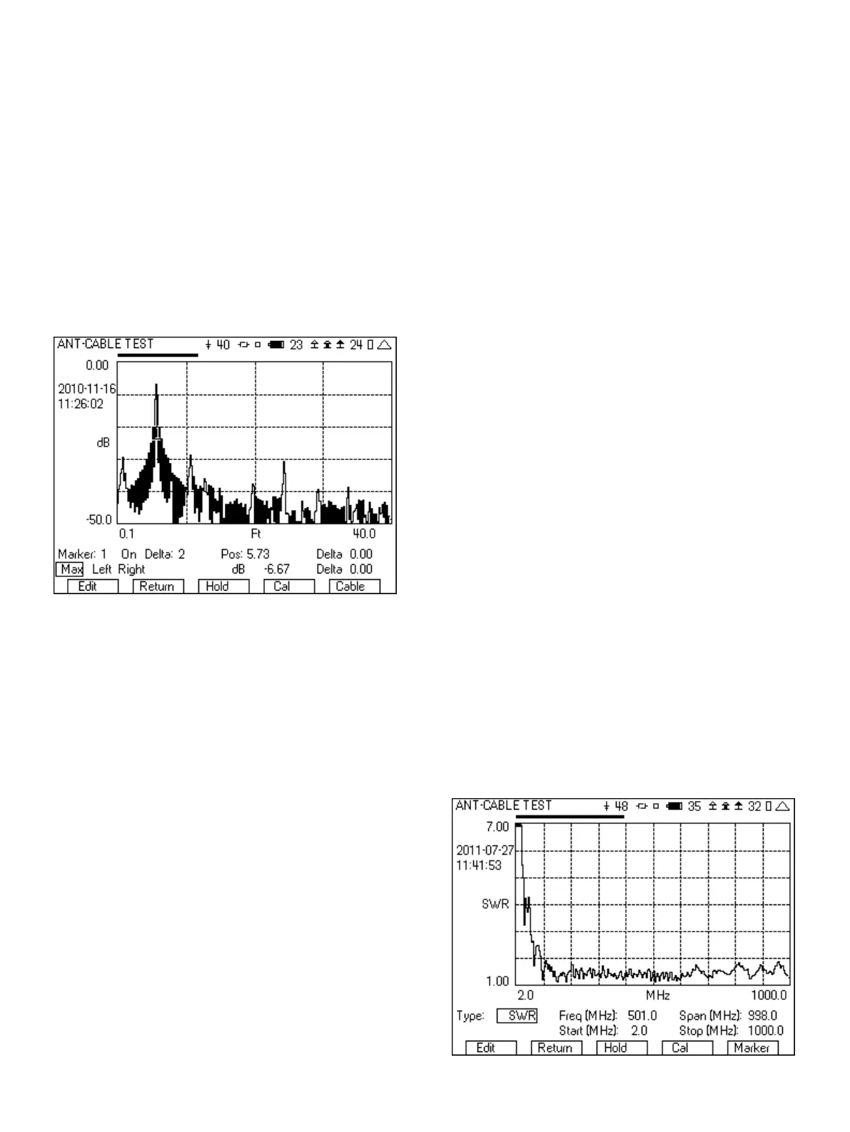
Figure 27 - Distance to Fault showing end of cable
The following is step by step instructions on setting up and
measuring the distant to fault.
1. From the System menu, select the ANT-CABLE TEST screen.
2. From the Type field select DTF (Distance To Fault).
3. Move the cursor to the Est Length field and select a value that is
at least 20% longer than what you think the length of your cable
is. The choices are 40, 80, 200 and 400 ft.
4. Using the far right softkey, change to the page that includes the
setup for the cable type.
5. From the list of cables, select the type of cable that you are
testing. If your cable is not in the list, then select USER. If
selecting USER, enter the Velocity factor and Loss per 100 ft in
dB. These two parameters can be determined by looking at the
specification for the cable. The velocity factor is the key
parameter for converting the time delay of the reflected signal
into distance. Since signals cannot travel at the speed of light in
a cable, the velocity factor is used to calculate the speed that the
signal is travelling.
6. Connect the cable that you are testing to the SWR port on the
3500A or to the test set cable and wait for two sweeps to
complete.
7. Your graph may now look like Figure 26 or Figure 27
depending on the fault(s).
8. Using the far right softkey, change to the Marker page.
9. Turn on Marker 1.
10. Move the cursor to the Max/Min/Move select field and select
Max. If Max is already selected, toggle through the list back to
Max. You will notice that as you toggle between Min and Max
the cursor will move between the maximum point in the trace
and the minimum point in the trace. There are several ways to
control the location of the marker.
a. The Pos field.
b. Toggling through Min, Max and Move.
c. Pressing the Enter key on Left and Right will move the
cursor to the next left or right Min/Max location, or if Move
is selected, will move it to the next left or right point.
11. If you selected Max, then Marker 1 should now be at the peak
of the graph. This peak may indicate the end of the cable, or it
may be indicative of a fault. Some faults will have more return
loss than the end of the cable and others may have less. The
determination of the faults in the cable though is the peaks in
the graph. So it is necessary to know the length of the cable to
distinguish the faults from the peak at the end of the cable.
12. If there is more than one fault in the cable, then turn on Marker
2 and move the marker to the location of the fault in the graph.
13. If you select a different cursor for Marker and Delta, then you
can see the delta difference between those two markers.
7.2 Measuring the Returns Loss or VSWR of an Antenna
1. From the System menu, select the ANT-CABLE TEST screen.
2. From the Type field select SWR (Standing Wave Ratio) or RL
(Return Loss).
3. Select the frequency range that you want to measure VSWR or
Return Loss. This can be selected with either the Freq and Span
field or with the Start and Stop field.
4. Connect the antenna or the cable leading to the antenna to the
SWR port.
5. Wait for two sweeps to occur.
6. Figure 28 shows an example VSWR sweep over the entire range
of the 3500A.
Figure 28 - VSWR sweep
16